A microcontroller can turn a pin on and off, but that’s usually where its strength ends. The moment you connect real hardware, things get messy. Without a proper driver like the ULN2003, even basic circuits stop behaving the way you expect.
Small motors refuse to start, buzzers draw too much current, LEDs dim under load, and coils create electrical noise that resets your system.
The practical fix is the ULN2003. It’s a seven-channel driver that lets your microcontroller control higher-voltage and higher-current loads safely.
It has built-in diodes to absorb motor spikes, supports up to 50 V and around 500 mA per channel, and each input connects directly to its matching output, which keeps wiring easy.
In this article, we cover the ULN2003 pin map and the specs that actually matter. We show clean wiring patterns for relays, lamps, and steppers.
Additionally, we will cover ULN2003 sequence for the 28BYJ-48, including wave, full-step, and half-step, so you can choose torque, smoothness, and speed with intent.
We then compare ULN2003 with close alternatives when efficiency and heat start to matter, and finish.
ULN2003 Overview
The ULN2003 is a popular seven-channel NPN Darlington transistor array used as a low-side driver for medium-power loads.
Each of the ULN2003’s seven outputs can handle about 500 mA of continuous current (up to 600 mA peak) and work with load voltages up to 50 V.
These limits make it a safe and reliable way to connect low-power microcontroller pins to real-world hardware such as relays, solenoids, stepper-motor coils, and LED strips.
The chip also includes built-in flyback diodes, which protect your circuit from the sharp voltage spikes created by motors and other inductive loads.
In practical terms, the ULN2003 works as a current amplifier: your microcontroller provides a small 3.3 V or 5 V control signal, and the ULN2003 handles the higher voltage and current that the device actually needs.
This keeps the MCU safe from overload and prevents damaged I/O pins.
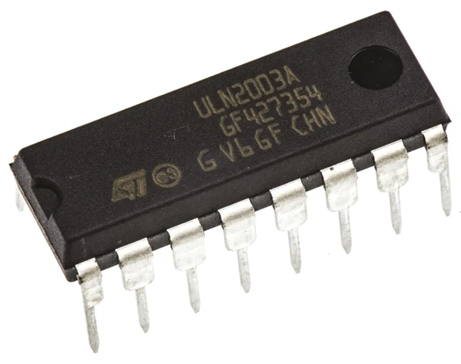
ULN2003 Pin Configuration
The ULN2003 may look like a simple 16-pin IC, but its internal layout is cleverly designed for clean PCB routing and predictable current flow.
Whether you’re wiring it on a breadboard or embedding it in a product, understanding the pin map helps avoid surprises. Lets dive into its layout:
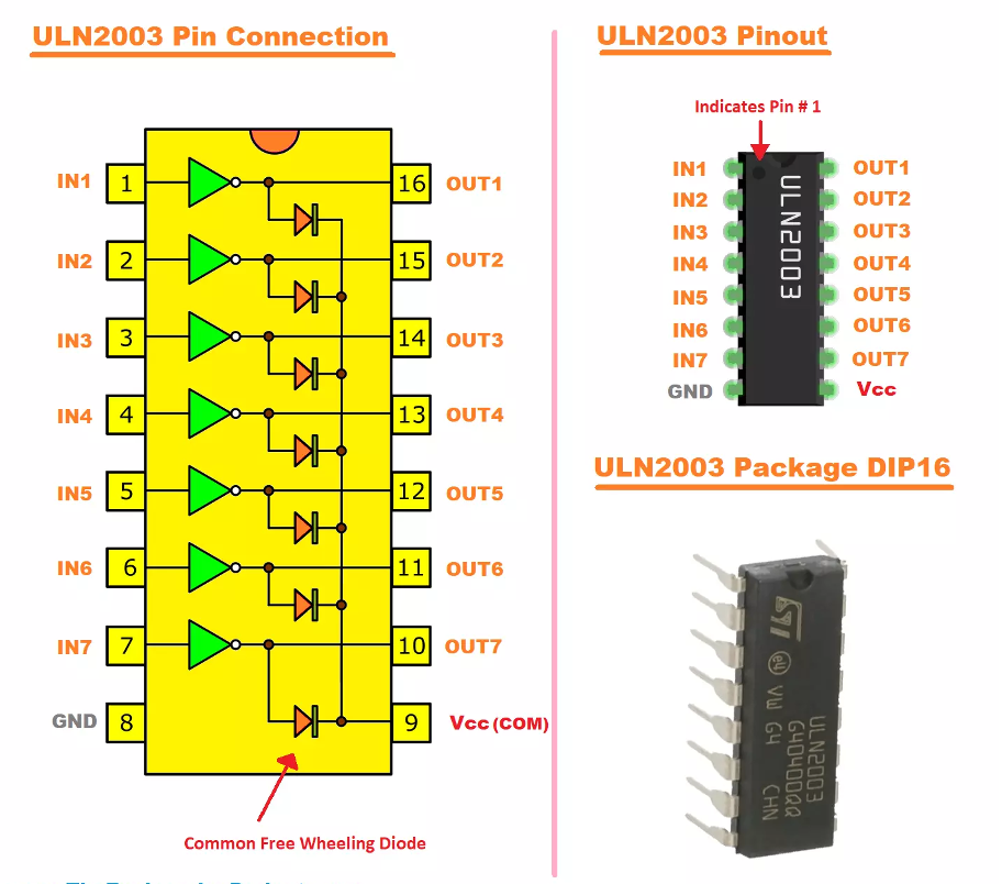
The 16-Pin Layout (DIP-16 / SO-16 / TSSOP-16)
The ULN2003 is typically packaged in a standard 16-pin body. The design is intentionally symmetrical:
- Pins 1–7: Inputs IN1 → IN7
- Pins 10–16: Outputs OUT1 → OUT7
- Pin 8: Ground (GND) shared by all channels
- Pin 9: COM (common diode cathode)
Each input on the ULN2003 is placed directly across from its matching output.
One of the most important parts of the ULN2003 is the COM pin. All seven of the chip’s internal flyback (clamp) diodes connect to this single point.
When you tie COM to the positive supply of your load, the ULN2003 can safely absorb voltage spikes caused by coils, relays, solenoids, and other inductive devices.
This is the built-in protection that keeps those spikes from reaching and damaging your microcontroller.
If COM is not connected when driving inductive loads, the circuit may appear to work at first, but you are effectively running without protection.
Over time, the repeated voltage spikes can destroy one of the transistors inside the ULN2003, leading to sudden failure.
Open-Collector Outputs
Each output pin (OUT1–OUT7) is an open-collector Darlington transistor pair. This means:
- The ULN2003 does not source current.
- It sinks current to ground when the input is high.
- When the input is low, the output floats (high impedance).
So the ULN2003 acts as a smart switch to ground, making it perfect for loads that expect one side tied to a power rail.
Inside Each Channel
Every one of the seven channels contains:
- Two NPN transistors in a Darlington configuration
- A bias resistor network
- A clamp diode (shared at COM)
- A 2.7 kΩ input resistor (in the ULN2003A version)
Input Behavior and Logic Compatibility
A major advantage of the ULN2003A is how easy it is to drive from any microcontroller. Each input already includes a 2.7 kΩ internal resistor, so you don’t need to add a separate series resistor.
The inputs work smoothly with 5 V TTL/CMOS logic, and a typical microcontroller pin only needs to supply around 0.25–0.5 mA per channel at 5 V.
In most cases, the chip also works reliably with 3.3 V logic, because the input thresholds for a TTL-level “high” are comfortably met.
The ULN2003 family also includes variants tailored to different input voltage ranges:
- ULN2001: 3–25 V logic
- ULN2002: 14–25 V logic
- ULN2003: TTL/5 V logic
- ULN2004: 6–15 V logic
ULN2003 Key Specifications
Before adding the ULN2003 to your design, it helps to understand its electrical limits, how much heat it can safely dissipate, and the wiring details that keep the driver predictable.
The ULN2003 is reliable, but as a Darlington array, it must be used within its thermal and electrical boundaries.
ULN2003 Electrical Limits: Voltage, Current, and Saturation Drop
Each channel is rated for up to 50 V and around 500 mA continuous (600 mA peak). These values look high, but they don’t apply when all seven channels are active.
The real constraint is the heat generated inside the IC. Because the outputs use a Darlington pair, they have a noticeable saturation voltage.
The drop is usually around 0.9–1.1 V at about 100 mA, 1.3–1.6 V at about 300 mA, and can reach ~2 V near the 500 mA limit.
This voltage is converted directly into heat, and a small 16-pin package cannot handle more than about a watt continuously.
For this reason, most designs keep long-term currents in the 200–300 mA range, unless multiple channels are paralleled.
Thermal Considerations
Different package types handle heat differently, and this affects how much current you can safely run.
| Package | Thermal Resistance (θJA) | Heat Rise at 1 W |
| DIP-16 | ~70 °C/W | +70 °C |
| SO-16 | ~65 °C/W | +65 °C |
| TSSOP-16 | ~93 °C/W | +93 °C |
A TSSOP version can approach 100 °C at around 0.8 W, while the DIP package stays cooler because of its larger leads and thermal mass.
When all seven channels are active, safe current often drops to around 125 mA per channel, depending on the manufacturer.
It’s also important to remember that the Darlington drop reduces the voltage available to your load.
A 5 V motor, for example, may only see roughly 4 V at higher currents, reducing torque and speed. If your load is sensitive to voltage, you should account for this loss during design.
Logic Compatibility
The ULN2003A is easy to interface with because its inputs are designed for 5 V TTL/CMOS logic and also work with 3.3 V microcontrollers.
Each input has a built-in 2.7 kΩ resistor, so there’s no need for external series resistors. At 3.3 V, the input current is roughly 0.7 mA
which is more than enough to drive a channel at typical loads.
If you’re working with logic levels above 5 V—such as 12 V CMOS—the safer option is the ULN2004A, which is designed for 6–15 V inputs.
The ULN2003 inputs themselves can tolerate up to about 30 V, giving some protection against wiring mistakes or noise.
Grounding and Layout
The ULN2003 is a low-side switch, which means all current returns through the single GND pin. Because of this, grounding quality directly affects performance.
Use a solid ground path, avoid long or narrow ground traces, and add decoupling near the load supply—typically a 47–100 µF capacitor along with a 0.1 µF ceramic.
Adding copper around the IC can also help if several channels carry higher current. For inductive loads like relays, solenoids, or motors, you must connect the COM pin to the load’s positive supply.
This connection allows the internal clamp diodes to absorb kickback safely. Leaving COM floating during inductive switching can damage the chip.
One final rule: ULN2003 outputs only sink current; they cannot source it. The correct wiring path is always:
+V → Load → ULN2003 Output → GND
If your design requires high-side switching, you’ll need a PNP transistor, a P-channel MOSFET, or a dedicated high-side driver.
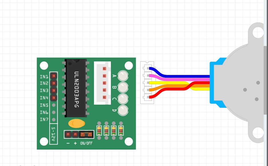
ULN2003 Driver Boards
ULN2003 driver boards make controlling small stepper motors especially the 28BYJ-48.
Instead of wiring individual coils or adding protection components yourself, the board integrates everything around the ULN2003A so you can connect the motor and start driving it with minimal setup.

The 5-Pin Motor Connector (JST-XH)
Most boards include a white 5-pin JST connector that matches the 28BYJ-48’s wiring. The four coil wires and the shared +5 V line are already routed to the correct ULN2003 outputs.
This eliminates the need to identify coil pairs or create your own cable, making the system essentially plug-and-play.
Four Input Pins (IN1–IN4)
On the other side of the board, the IN1–IN4 header connects directly to your microcontroller’s GPIO pins.
Since the 28BYJ-48 is a four-phase stepper, only four of the ULN2003 channels are used. A simple jumper cable set is all you need to begin sending step commands.
Built-In Output Indicator LEDs
Many boards include four indicator LEDs, one tied to each motor coil output. When a channel activates, its LED lights up.
These indicators are helpful during setup and testing because they let you quickly confirm the stepping pattern, direction changes, and timing without requiring the motor to be plugged in.
Optional ON/OFF Jumper
Some variants add a small ON/OFF jumper for the motor’s 5 V line. Pulling the jumper cuts motor power instantly while leaving the control pins untouched.
This acts as a simple safety switch during debugging or when you want to prevent unexpected motor movement.
Power Pins: VCC and GND
Although the ULN2003 itself is a low-side driver, the board includes +5 V and GND terminals to supply the motor.
It’s generally better to power the motor from a dedicated 5 V source rather than a microcontroller regulator.
The board ties all grounds together so the logic signals remain stable, and the +5 V line feeds both the motor connector and the board’s diode network.
The ULN2003A IC (Center of the Board)
The ULN2003A is usually mounted in a DIP-16 socket, making it easy to replace if a channel is damaged during testing.
On most boards, the COM pin is already connected to the motor’s +5 V line, so the flyback diodes have the correct reference and inductive loads are safely handled without any extra wiring.
ULN2003 Sequences for 28BYJ-48
Driving a 28BYJ-48 unipolar stepper motor with a ULN2003 board comes down to one core idea:
energize the motor coils in the correct sequence.
The pattern you choose affects torque, smoothness, noise, and speed.
The 28BYJ-48 stepper motor is a 4-phase motor, so we control it through IN1–IN4, each turning one of the four coils on or off. The ULN2003 simply sinks current for each coil as your microcontroller activates the pins.
There are three classic drive modes used with this motor: Wave Drive, Full-Step Drive, and Half-Step Drive.
1. Wave Drive (Single-Coil Excitation)
Wave drive is the simplest pattern: only one coil is energized at a time. The sequence moves from coil A → B → C → D, then repeats.
This mode has the lowest power consumption because only one coil is active on each step. It also offers the lowest torque, since the rotor has only one magnetic pull direction at any given moment.
Typical characteristics:
- Lowest current draw
- Minimum holding torque
- Lightest torque during rotation
- Each internal step is roughly 11.25° (before gearbox)
- Smooth enough for basic low-load applications
Wave drive can spin the motor a bit faster due to less magnetic drag, but it lacks the strength needed for most real-world loads.
2. Full-Step Drive (Two-Coil Excitation)
Full-step mode energizes two coils at the same time. The sequence looks like A+B → B+C → C+D → D+A.
Because two magnetic fields overlap, torque is significantly higher compared to wave drive. The step angle is still 11.25°, but the motor holds its position better and transitions between steps with more authority.
Key points:
- Higher torque and stronger holding force
- Slightly rougher movement than wave drive
- Double the current draw (two coils energized every step)
- Same step angle as wave drive, but stronger performance
Full-step mode is ideal when you need extra torque without needing smoother motion.
3. Half-Step Drive (Most Common and Recommended)
Half-step mode alternates between one coil and two coils energized. The result is eight positions per full cycle instead of four.
Sequence example:
A → A+B → B → B+C → C → C+D → D → D+A → repeat
This effectively cuts the internal step angle in half to 5.625° (again before gearbox). This finer step angle, combined with more consistent torque delivery, produces a smoother and quieter motion.
Why half-step is preferred:
- Smoother rotation
- Higher positional resolution
- Better torque than wave drive
- Less vibration at low speeds
- Average current consumption (between wave and full-step)
After the stepper’s internal gearing (around 64:1), half-step mode usually produces 2048 steps per output shaft revolution. Some variants have slightly different gear ratios, so you may see 4096 steps/rev in some references. Different manufacturers choose different ways to count internal steps, so calibration is recommended for precision projects.
In real use, half-step drive is the sweet spot. It delivers:
- Smooth motion
- Stable torque
- Good low-speed control
- Less resonance
- Finer movement resolution
Wave drive is useful for ultra-low-power applications, while full-step is good for maximum torque. But for most projects, half-step gives the nicest balance, which is why nearly all tutorials and Arduino libraries use it by default.
4. Direction Control
Changing the direction is simple:
reverse the order of the sequence.
Example (half-step):
- Forward: A → A+B → B → B+C → C → C+D → D → D+A → repeat
- Reverse: A → D+A → D → C+D → C → B+C → B → A+B → repeat
The ULN2003 doesn’t handle direction itself. It just follows the input pattern. All direction logic lives in your microcontroller code.
5. Timing and Step Rates
The 28BYJ-48 is a low-speed, high-torque geared motor. Your timing between steps affects:
- Torque
- Speed
- Whether the motor stalls or skips steps
Typical delay values:
- 2–10 ms per half-step
- Corresponds to roughly 500–125 Hz
Start with slower step rates, then gradually increase speed. If you step too fast from a standstill, the motor may fail to move and lose synchronization with your sequence.
Because the motor has a gearbox, final rotation speed is modest. With 5 V supply and half-step drive, expect:
- roughly 10–15 RPM at the output shaft under light load
Faster speeds require careful acceleration or different driver hardware.
Case Study: ULN2003 vs ULN2803
The ULN2003 and ULN2803 are both Darlington transistor arrays designed for driving relays, solenoids, lamps, and small motors.
Electrically, they behave almost the same, but their differences matter once you consider channel count, layout, heat, and ecosystem support.

1. Core Differences at a Glance
| Feature | ULN2003 | ULN2803 | Why It Matters |
| Channels | 7 | 8 | ULN2803 maps perfectly to 8-bit MCU ports |
| Use Cases | Stepper boards, small loads | Relay banks, multi-output control | Depends on load count |
| Board Ecosystem | Very strong (28BYJ-48 kits) | Strong in relay modules | Affects convenience |
| Thermal Load | Spread across 2 ICs if needed | Concentrated in one IC | ULN2003 may run cooler |
Both support: 50 V outputs, 500 mA per channel, built-in diodes, TTL logic drive, and similar V<sub>CE(sat)</sub>.
2. Scenario A: 8-Relay Bank (12 V, 120 mA per relay)
ULN2003
- Needs two chips to support 8 relays
- Heat is distributed (safer thermally)
- More PCB area and wiring
ULN2803
- One chip handles all 8 relays
- Cleaner wiring and simpler PCB
- Higher thermal density (can get warm)
Choose ULN2803 for cleaner design, ULN2003 if heat margins matter.
Scenario B: Driving the 28BYJ-48 Stepper Motor
ULN2003
- Dedicated stepper driver boards available
- Correct JST connector for motor
- Libraries, examples, and coil mapping already standardized
ULN2803
- No standard “ULN2803 stepper board”
- Requires manual wiring and mapping
- No functional advantage
ULN2003 wins for stepper motor applications due to ecosystem and convenience.
Which One to Select?
Selection depends on your project needs. The ULN2003 is the ideal option when driving 4–7 loads, controlling the 28BYJ-48 stepper motor, or spreading thermal load across multiple packages.
It is also more convenient during prototyping because DIP versions are easy to replace. The ULN2803 is more suitable when you need exactly eight outputs and want neat one-to-one mapping from a microcontroller’s 8-bit port to eight driven loads.
If efficiency, low heat, or 3.3 V logic compatibility is important, modern DMOS drivers such as ULN2003V12 or Toshiba’s TBD62083A offer significantly lower voltage drop and cooler operation, making them better choices for dense or power-sensitive designs.
Electrically, ULN2003 and ULN2803 are nearly identical. The real differences come down to:
- Channel count
- Thermal distribution
- Board ecosystem
- Ease of wiring
ULN2003 is the better choice for steppers and small projects. ULN2803 is ideal for 8-channel relay drivers and compact multi-output control. For modern, efficient designs, a DMOS driver is the best upgrade.
Final Thoughts
The ULN2003 is, at its core, a simple and reliable Darlington transistor array, built to let microcontrollers safely control real-world loads.
By combining seven Darlington pairs and built-in flyback diodes in one package, it handles the current and protection tasks that microcontroller pins cannot.
With the 28BYJ-48 stepper motor, the ULN2003 forms a compact and beginner-friendly motion system.
Once the wiring, grounding, and COM connection are correct, the motor responds cleanly to wave, full-step, or half-step patterns, giving you predictable torque and smooth rotation.
Because Darlington arrays drop more voltage and generate more heat, the ULN2003 is best suited for low-power motors, relays, LEDs, and small automation tasks.
For applications that need higher efficiency or stronger torque at the same input voltage, newer DMOS-based versions—such as the ULN2003V12—offer lower losses and better performance with 3.3 V logic.
Package choice also plays a role. DIP versions are easier to prototype and handle heat better, while SOIC and TSSOP options save board space but require careful current planning.
TI and ST both produce several variants, including automotive-qualified versions and updated MOSFET arrays like ULN2003V12PWR. Always confirm the voltage, current, and package thermal ratings before selecting a drop-in replacement.
If you’re ready to pick up a ULN2003 or explore its newer MOSFET equivalents, you can browse the full range on Flywing Tech. We carry the classic ULN2003A in DIP and SOIC packages as well as newer low-loss options like ULN2003V12.
Each product page includes datasheets, package details, and electrical specs so you can match the driver to your exact load, whether it’s a relay bank, a small motor, or a compact automation module.
Explore ULN2003 and ULN2003V12 driver ICs on Flywing Tech and choose the right solution for your next project.
FAQs
General Questions
The ULN2003 is a seven-channel Darlington transistor array used for driving relays, solenoids, lamps, LED strings, and small motors. It works as a low-side driver, meaning it sinks current from the load to ground. Each channel includes a built-in flyback diode, making it ideal for inductive loads like relays and stepper motors.
The 28BYJ-48 can be driven using three common ULN2003 sequences: wave drive, full-step, and half-step. Wave drive energizes one coil at a time, full-step energizes two coils at once, and half-step alternates between the two. Half-step is the most popular because it offers smoother motion and finer positioning.
Yes, in most cases. The ULN2003A’s inputs use 2.7 kΩ resistors and can usually be driven from 3.3 V logic as long as the required load current isn’t extremely high. For guaranteed 3.3 V compatibility, modern MOSFET-based versions like ULN2003V12 or TBD62083A are even better choices.
28BYJ-48 Stepper Motor
Yes. The ULN2003 datasheet allows you to tie two or more outputs in parallel and drive them with the same input signal. This helps share the load across multiple Darlington channels. It isn’t perfect current sharing, but it works well for moderate increases in current. Be mindful of total package heat.
Just reverse the order of the coil sequence. The ULN2003 doesn’t know anything about step direction. Your microcontroller controls direction by sending the stepping pattern forward (A → B → C → D) or backward (A → D → C → B).
Generally no. The 28BYJ-48 can draw 200–300 mA when stepping, which is more than most MCU regulators can safely supply. Use an external 5 V supply for the motor and keep the grounds connected. The ULN2003 board ties the grounds together internally.
Compatibility & Upgrades
Choose the ULN2803A when you need eight channels instead of seven. Electrically, it behaves nearly the same as the ULN2003A and is often used when driving an 8-relay board or other 8-bit loads. It’s essentially an expanded ULN2003.
DMOS drivers are superior when you need lower heat, lower voltage drop, and better efficiency. They deliver more voltage to the load and waste less energy as heat compared to Darlington arrays. This matters in battery-powered devices, dense relay banks, or any application where thermal management is tight.
Yes, if you are driving inductive loads like relays, solenoids, or stepper motors. COM must be tied to the positive supply of the load so the internal flyback diodes can clamp voltage spikes safely. For purely resistive loads (like LEDs), COM can be left unconnected.
No. The ULN2003 only sinks current to ground. If you need high-side switching (sourcing current to the load), you’ll need different circuitry such as a PNP transistor, a P-channel MOSFET, or a dedicated high-side driver IC.