Introduction
The LM386 is an 8-pin audio amplifier IC that is widely used in low-power, portable audio applications, including electronic clocks, FM radios, doorbells, telephones, and small speakers. LM386 is low cost, widely available, and requires minimum external components, making it a suitable solution for audio amplification applications. The LM386 audio amplifier mostly comes in a DIP package with a supply voltage range of 4V-12V, and a voltage gain of up to 200.
Normally, the voltage gain of LM386 is 20. However, with the addition of an appropriate resistor and capacitor value on PIN 8 and PIN 1 (Gain), the gain can be increased up to 200. It only requires a few volts, i.e., 4V, that can be supplied from a simple battery. Therefore, whether you are a hobbyist, an engineering student, or an electrical professional, LM386 provides a low-cost and reliable solution for audio amplification applications such as DM radios, tone generators, DIY audio amplifiers, and low-voltage commercial applications.
What is the LM386 Audio Amplifier and Why Do We Use it?
LM386 is a low-power audio amplification device that is primarily use for the amplification of audio signals. This audio amplifier IC operates with low voltage (minimum of 4V) and, therefore, is most suitable for portable audio and battery-operated audio electronic devices.
High power amplifiers require high operating voltage, a complex external circuit, and heat sinks to prevent overheating of the IC. Whereas, LM386 requires a minimum external circuit, and uses only 4V for powering up, and has no requirement for a heat sink. Its operating supply voltage range is between 4V-12V with an output power between 325 mW to 700 mW.
The LM385 audio amplifier provides a decent voltage gain of between 20-200. The internal circuit of the LM386 makes the device gain 20. However, with a proper selection of only one external resistor and capacitor, one can adjust it to a maximum of 200. One resistor and capacitor is use between pin 1 and pin 8 for gain adjustment.
LM386 has adjustable voltage gain, low operating voltage, output power between 325mW and 700mW, and no requirement for a heat sink. Therefore, making it perfect choice for enginers to use it in low-voltage consumer applications, including AM-FM radio amplifiers, portable audio devices, TV sound systems, ultrasonic drivers, and intercoms.
LM386 PIN Configuration
The LM386 audio amplifier IC is manufactured by Texas Instruments (TI) and comes in various packages, i.e., PDIP, SOIC, and VSSOP. The device only has 8 pins with a simple circuit structure and minimum external component requirements. Designers and electronic enthusiasts should have a solid understanding of each pin to utilize it in different circuit design applications efficiently. So, to avoid any mistakes in your circuit application, make a solid grip on the function and purpose of each LM786 pin.
Pin Configuration of the LM386 Audio Amplifier IC

Internal Circuit & Working Operation
LM386 is a high-gain adjustable voltage gain amplifier that is specifically design to drive small speakers with a minimum external component requirement. The internal circuit of LM386 consists of three stages: an input stage, a voltage gain amplifier stage, and an output stage, as shown in the simulation circuit below.

Input Differential Amplifier Stage
In the first stage, the input audio signal is given between PIN 2 and PIN 3, known as the differential inputs. The input biasing resistors of 50kΩ at both inputs provide proper DC operating conditions. This first stage consists of a differential amplifier that takes the audio input signal and amplifies the difference between the inverting and non-inverting inputs, and rejects the common mode. The output of this stage provides the initial voltage gain and improves the signal-to-noise ratio (SNR).
Voltage Amplifier Gain Stage
The second stage consists of a voltage gain amplifier. The output from the previous stage acts as the input to this voltage gain amplifier. This stage provides the main amplification of the input signal. By default, the voltage gain of the LM386 is 20. However, by using a capacitor of 10uF between the pins of 1 and 8, one can adjust it to maximum of 200. A bypass capacitor at pin 8 with reference to the GND pin provides stability and reduces the power supply noise.
Output Stage
The third stage consists of an AB push-pull output stage. The purpose of this stage is to provide sufficient current to drive the loads, such as small speakers. The LM386 provides the output on the pin 5 (Vout). This stage uses complementary transistors to provide the amplified signal such that it can drive 8 8-ohm speaker with up to 1W of output power. So, LM386 is perfect for low-voltage audio amplifications such as portable audio devices, AM-FM radio amplifiers, and TV sound systems. For more in-depth analysis and illustration go through this video on LM386 audio amplifier.
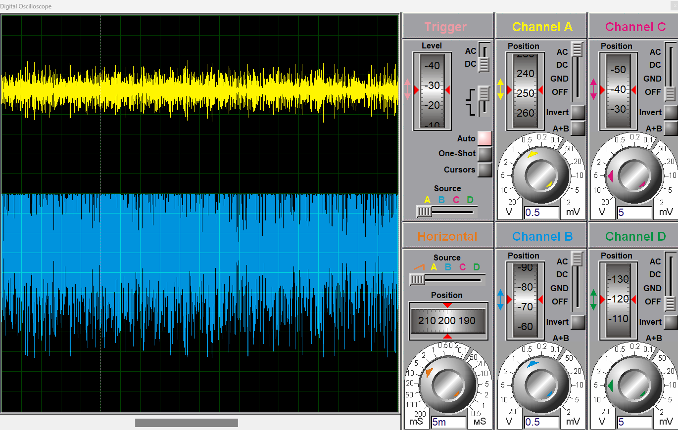
The figure below shows the input and output waveforms of the internal circuit of the LM386.

The diagram below shows the flow diagram of LM386 along with three stages are their purposes.

Technical Specifications & Parameters
The LM386 audio amplifier consists of 8 pins and mostly comes in DIP, SOIC, and VSSOP packages. There are various variants of LM386; always consult the datasheet for accurate information and the defined limits of parameters. In this section, I will explain some of the core technical parameters of LM386. These technical parameters will help you in designing the low-voltage applications with LM386. Without having the technical knowledge of the technical specifications of LM386, one can end up damaging the LM386 or causing improper behavior of the design application.
Technical Specifications of LM386 Audio Amplifier
Circuit Design Considerations
When designing audio applications with LM386, it is important to follow key design considerations. LM386 is a low-voltage audio amplifier; therefore, a small change or variation can significantly affect the performance or functioning of design application. In this section, I will explain some of the key design considerations while designing with the LM386 audio amplifier. Adaptation of key design considerations, such as biasing, grounding, and component placement, can significantly increase the design performance, decrease the noise levels, and increase the overall efficiency.
Power Supply and Decoupling
LM386 is a versatile audio amplifier that has a wide adjustable voltage gain range. It has a supply voltage range between 4V and 12V. It can be power up from even a battery. We connect the supply voltage on pin 6 (VS) with reference to pin 4 (GND). LM386 is a low-voltage audio amplifier, and therefore, small variations in the voltage can greatly affect the performance or even damage the device. Therefore, to prevent the device from noise and voltage fluctuations, a decoupling capacitor of 100uF is use across the VS with reference to GND.
Gain Setting
By default, the LM386 is set with a gain of 20. However, with the external components it can be increase to 200. By using a 10uF capacitor across the PIN 1 and PIN 8 (gain setting pins) of the LM386, the gain will be increased to 200. However, it is worth mentioning that with an increase in gain, the noise will also amplify. Therefore, designers should trade off between higher gain and stability, depending upon the specific application. For most low-power applications, a gain of 100 works well.
Input Coupling & Signal Filtering
It is always best practice to use the 10uF coupling capacitor in series with the input signal. This capacitor blocks the DC component and only allows the AC component to enter the amplifier. A combination of a resistor and a capacitor (RC) circuit can also be used to make a high or low pass filter. Use of a low or high pass filter is often effective when you need to limit the unwanted frequency ranges.
Output Coupling
At the output of LM386, connect another capacitor of 200uF or greater. This capacitor blocks any DC content and only allows the AC signal to pass through the load, i.e., speaker or headphones. A bypass capacitor across pin 7 (bypass) and GND is also use to improve the overall gain of the LM386. Whenever you want to increase the gain by means of a capacitor across pin 1 and pin 8. You also need to connect the bypass capacitor across pin 7 with reference to GND.
Grounding & Layout
In printed circuit boards, proper grounding is important to prevent noise and electromagnetic interference. In circuit boards, signal GND and power ground should always meet at a single ground to prevent ground loops. Always place the coupling capacitor near the supply pin to avoid signal loss and electromagnetic interference.
Typical LM386 Circuit Designs with Simulations
LM386 is use in various audio amplification applications, like intercom systems, AM-FM radio systems, tone generator circuits, noise filtering, and ultrasonic drivers. In this section, I will explain and simulate some of the basic application circuits with the LM386 audio amplifier. This section will help you introduce the real-world applications and their implementation. I have use Proteus software to simulate the basic application circuits with LM386.
Basic Low-Gain Audio Amplifier
One of the simplest and basic applications of the LM386 is a low-gain audio amplifier. This circuit consists of an LM385 IC, a speaker, a mic, and some external components like resistors and capacitors. A basic low audio circuit is designed for small signal amplification. Typically, we can drive an 8-ohm speaker from a low-gain audio amplifier.
We have use LM386 in the default gain configuration, which is 20. Therefore, pins 1 and 8 of LM386 are left open. An input audio file (.wav file) is given as an input to LM386 at pin 3 with a potentiometer. Connect the +5V input supply to pin 3 of LM386.
Place a coupling capacitor of 1nF is on pin 3 with reference to GND to block any DC content and only allow the audio signal. Now, connect another capacitor, known as the bypass capacitor of 1uF, on pin 7 with reference to GND to reduce noise and improve stability, as shown in the figure below. Connect the 8-ohm speaker to the output pin 5 of the LM386. Now, place a coupling capacitor of 220uF is before the speaker/load to block any DC offset. The protues software figures below shows the circuit diagram, along with its input and output waveforms.


High-Gain Audio Amplifier
In this application circuit, I have designed a high-gain audio amplifier by using the maximum gain feature of the LM386 audio amplifier. Unlike in the previous application circuit, pin 1 and pin 8 are not left blank. LM386 offers a maximum of 200 gain by using the resistor and capacitor between pin 1 and pin 8. To achieve maximum gain, connect the 10uF capacitor and 10-ohm resistor between pin 1 and pin 8 as shown in the circuit diagram shown below.
Connect the +5V supply to pin 6 with reference to GND (PIN4). The audio file (.wav file) is use as an input to this LM386 amplifier for amplification. The amplified audio signal appears at the output pin 5 of LM386. Connect a 1nF coupling capacitor (C2) at the input terminal to block DC content and allow only the AC audio signal. Connect another coupling capacitor (C5) before the output goes into the speaker to block any DC offset and allow only the audio signal.
The circuit diagram, along with its audio input and output waveforms, is shown in the figures below.

Audio Power Amplifier Test Circuit
Apart from just audio amplification, LM386 can also be use as a test circuit to evaluate frequency response, or waveform behavior. These test circuits are widely use in applications like laboratory testing, prototype verification, and educational demonstrations.
In this application, different input waveforms such as sine wave, square wave, and triangular wave are use as an input to the LM386. A coupling capacitor of 220nF is use to remove the DC content from the test signals and only allows the exact test signal to pass through the amplifier input. Connect the 10kΩ potentiometer at the input terminal (PIN 3) with reference to GND to control the volume or attenuation. The output appears at pin 5 of LM386. The output of pin 5 drives the 8Ω speaker. A coupling capacitor is also use to block the DC offsets and allows only the amplified test signals to go into the speaker. The output waveforms and circuit diagrams of Proteus are shown in the figure below.


Advantages and Limitations of the LM386 Audio Amplifier
Like any electronic device, there are advantages and some limitations. The LM386 was first introduced in 1970, and since then, it has been widely used in various audio amplification circuits. However, with time, there are more powerful audio amplifier ICs are continuously emerging in the market. Therefore, using LM386 audio amplifiers comes with its own advantages and limitations. In this section, I have list down some of the key advantages and limitations of using LM386. These help the designers to trade off between advantages and limitations for their specific application design.

LM386 VS Alternatives
LM386 was introduced in 1970, and since then there are a lot of audio amplifier ICs have been introduced in the market. When designing audio applications, it is important to get familiar with different audio amplifier ICs available. This way, designers can easily decide which audio amplifier fits best for their specific application. In this section, I will explain some of the alternatives to the LM386 audio amplifier. Some of the widely available and used alternatives are LM380 and LM4871.

Troubleshooting
LM386 is a low-voltage amplifier, and that means even a small voltage fluctuation can lead to noise or distortion in the output. When dealing with the LM386 audio amplifier, minor problems can affect the overall functionality of the design application. In this section, I will explain some of the most frequently and commonly occurring errors in LM386.
Troubleshooting Common Problems of LM386 Audio Amplifier
Conclusion
In conclusion, LM386 is a versatile, powerful, and low-voltage audio amplifier IC that is widely use in various audio amplification applications, including AM-FM radio amplifiers, ultrasonic drivers, tone generators, TV sound systems, intercoms, portable speakers, and many more. Understanding its pinout, circuit design, internal circuit, and working operation is essential for hobbyists, design professionals to efficiently design their intended applications. Its straightforward interface with minimum external components requirement and ability to adjust gain make it perfect for a range of audio amplification applications.

Frequently Asked Questions (FAQ)
Q1. What is the typical gain of LM386?
The LM386 audio amplifier has an adjustable voltage gain between 20-200. By default, LM386 is set to a gain of 20. However, with an external resistor and capacitor between pin 1 and pin 8, the gain can be increase up to 200.
Q2. Why do we need to connect the capacitor to pin 7 of the LM386?
Pin 7 of LM386 is known as the bypass pin. Connecting a capacitor to this pin reduces the power supply noise and improves stability.
Q3. How to reduce noise in the LM386 audio amplifier?
To eliminate the noise from the LM386, always to use a decoupling capacitor on the supply pin 6 (VS) with reference to GND. Also, place a bypass capacitor on pin 7 of the LM386 to reduce power supply noise.
Q4. What is the maximum operating voltage of LM386?
LM386 is a low-voltage audio amplifier, and it has an operating voltage range between 4V and 12V.
Q5. Can LM386 drive headphones or earphones?
Yes, LM386 can easily drive loads greater than 8Ω. Headphones have high impedance, and thus LM386 can easily drive them.
Q6. Can I use LM386 for stereo applications?
Yes, one can use LM386 for stereo applications. However, for stereo applications, we need to use two LM386 audio amplifier ICs. One for the left channel and one for the right channel to create a compact dual-channel stereo system.