Every control panel, distribution board, and piece of industrial equipment eventually comes down to the same question: how do you join wires together safely, without soldering, and in a way that someone can service five years from now without guessing what goes where? That’s the job terminal blocks do.
A good terminal block connector turns a tangle of bare conductors into an organized, labeled, serviceable connection point, and it does it without a single drop of solder or a permanent splice you can never undo.
This guide walks through what a terminal block actually is, how the different types work, how to wire and select one correctly, and where people most often get it wrong.
What Is a Terminal Block?
A terminal block is a modular electrical component that connects two or more wires at a single, reusable junction point.
Instead of twisting conductors together and capping them, or soldering them into a permanent joint, you clamp each wire into its own terminal.
The connection is mechanical, it’s solid, and unlike a solder joint, it can be opened back up whenever the wiring needs to change.
Strip away the variations in shape and mounting style, and every electrical terminal block is built from the same basic ingredients:
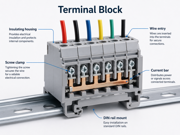
- Insulated housing: A molded plastic or, in some cases, ceramic body that holds the conductive parts and keeps adjacent terminals from touching each other.
- Conductive metal components: Usually a copper alloy or brass current bar that actually carries the electrical current from one wire to the next.
- Wire-entry points. Openings sized for a specific range of wire gauges, where the conductor goes in.
- Clamping mechanism: The part that physically holds the wire in contact with the current bar, whether that’s a screw, a spring, a lever, or a push-in design.
- Modular construction: Many terminal blocks, especially DIN rail terminal blocks, are designed to snap together side by side, so you can build a custom terminal strip exactly as long as your application needs.
If you’re specifying terminal blocks for a control cabinet, a machine build, or a distribution panel, you’ll find the technical grounding here to make the right call. For the parts themselves, Flywing Tech stocks the full range across barrier blocks,DIN rail terminal blocks,PCB and wire-to-board styles, andaccessories.
Main Parts of a Terminal Block
It helps to know what each piece is actually doing, especially when you’re troubleshooting a connection that’s gone bad.
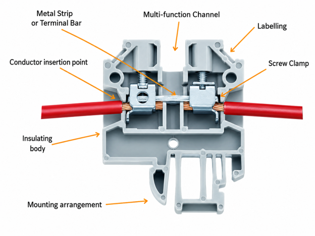
- Housing: the outer insulating shell. It’s what protects people from accidental contact with live metal and keeps the terminal block from shorting against the panel or adjacent components.
- Current bar: the internal conductive strip the wire presses against. This is where the real current-carrying happens, and its material and cross-section determine how much current the terminal can handle.
- Clamping screw or spring: the mechanism that applies pressure to keep the wire seated firmly against the current bar. A loose clamp is the single most common cause of terminal block failure in the field.
- Wire entries: the physical openings where conductors are inserted. Their size dictates the minimum and maximum wire gauge the terminal will accept.
- Mounting foot: the part that locks the terminal block onto a DIN rail or secures it to a panel.
- End covers and separators: accessories that close off the ends of a terminal strip and, where needed, add extra insulation between adjacent terminals carrying different voltages or phases.
- Marking labels: small inserts or printed surfaces used to identify each terminal, which matters enormously once you’re staring at forty terminals in a control cabinet trying to trace a fault.
How Does a Terminal Block Work?
The working principle behind a terminal block connector is straightforward, even if the engineering behind it isn’t.
The conductor goes in, gets clamped against a conductive bar, and current flows through that bar to whatever’s connected on the other side.
Here’s the basic current path, step by step:
- The wire enters the terminal through its designated opening, stripped to the correct length so bare copper, not insulation, makes contact with the metal.
- A screw, spring, or lever clamps the conductor against the current bar, creating a low-resistance mechanical and electrical connection.
- The conductive bar carries current between the connected terminals, sometimes to a single opposing wire, sometimes distributing it across multiple connection points on the same block.
- The housing prevents accidental contact with live parts and keeps adjacent terminals electrically isolated from one another, which is what makes the whole system safe to work around.
This is the principle behind how do terminal blocks work in every variation you’ll come across, from a simple two-position screw terminal to a multi-level DIN rail terminal block carrying dozens of circuits.
Terminal Block vs Terminal Strip
People use “terminal block” and “terminal strip” almost interchangeably, and in casual conversation that’s fine.
But there’s a real distinction worth knowing, especially if you’re searching a catalog or reading a datasheet.
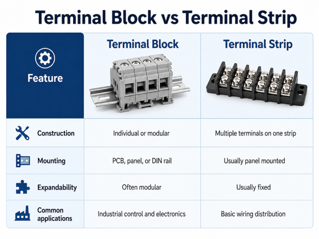
A terminal block usually refers to an individual or modular connection point, something you can mount on its own or snap together with others on a DIN rail to build whatever length you need.
A terminal strip, by contrast, typically describes multiple terminals already mounted together on one fixed base, often used in simpler wiring distribution jobs rather than dense industrial control panels.
If your project needs flexibility to add or remove circuits later, modular terminal blocks on a DIN rail will serve you better than a fixed terminal strip.
If you just need a handful of fixed connection points and don’t anticipate changes, a terminal strip can be a simpler, more economical choice.
Flywing Tech carries both: browse terminal strips and turret boards alongside the modular DIN rail lineup.
Common Types of Terminal Blocks
Terminal blocks split into categories two different ways: by how the wire gets clamped in (the connection technology) and by what the block is built to do (the application).
Here’s a rundown of the major types you’ll encounter.
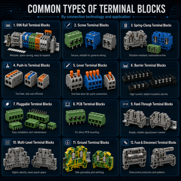
DIN Rail Terminal Blocks
DIN rail terminal blocks are modular blocks designed to snap onto standard DIN rails inside control cabinets and electrical enclosures.
Instead of mounting each terminal individually, installers can build a complete row of terminals on one rail, add or remove blocks as needed, and keep wiring organised with labels and accessories.
They are commonly used in industrial panels, PLC systems, automation equipment, distribution boards, and machinery wiring.
The most common rail profile is the TS35 top-hat rail, while TS32 and TS15 rails are used in heavier-duty or compact installations.
DIN rail systems also support accessories such as end stops, end covers, jumpers, marking strips, separators, test plugs, and distribution bridges.
These accessories make it easier to secure the terminal row, label circuits, distribute power, and test wiring without disturbing the rest of the panel.
Screw Terminal Blocks
The most familiar design, and still the workhorse of industrial wiring.
A screw threads down and clamps the conductor directly against the current bar, or against a pressure plate that distributes clamping force evenly across the wire strands.
Screw terminals are reliable, inexpensive, and easy to inspect visually, since you can usually see whether a screw is properly seated.
Suitable for:
- Control panels
- Power distribution
- Industrial equipment
- Building wiring
Spring-Clamp Terminal Blocks
Instead of a screw, a spring-clamp terminal uses constant spring tension to hold the wire in place.
You open the clamp, usually with a small lever or screwdriver, insert the wire, and release. The spring does the rest, maintaining steady contact pressure indefinitely without needing periodic re-tightening.
This makes spring-clamp designs a strong choice in environments with vibration, where a screw might gradually work loose over time.
Push-In Terminal Blocks
Push-in terminal blocks take the spring-clamp principle one step further: you simply push the stripped wire straight into the opening, and an internal spring contact grips it automatically. No tool, no lever, no screwdriver.
They’re popular wherever fast, repeatable installation matters, like high-volume panel assembly, because there’s effectively zero room for inconsistent torque between one terminal and the next.
Lever Terminal Blocks
Lever terminal blocks add a small actuating lever that opens and closes the internal spring-clamp mechanism.
Flip the lever up, insert the wire, flip it back down, and the spring clamps shut.
They combine the vibration resistance of a spring connection with tool-free, repeatable operation, which is why they’ve become common in machine builds where technicians need to swap wiring quickly during commissioning or maintenance.
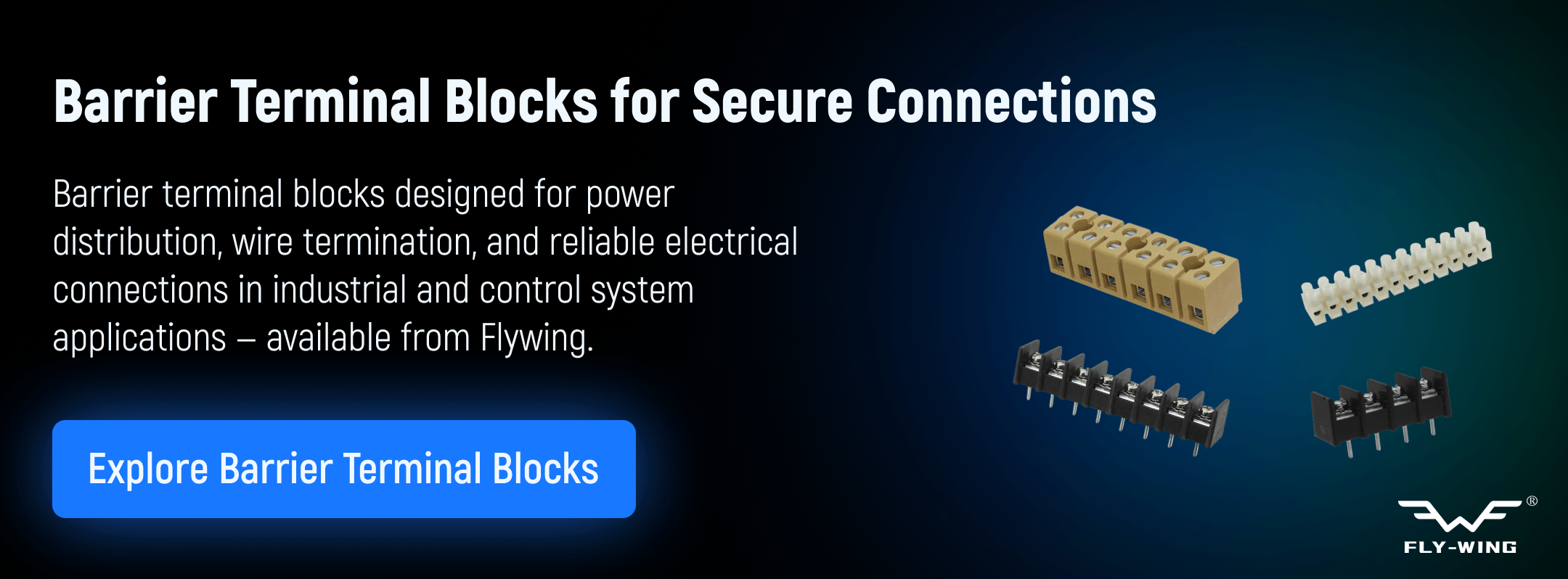
Barrier Terminal Blocks
Barrier terminal blocks add raised insulating walls between each terminal position.
Those barriers increase the creepage and clearance distance between adjacent connections, which matters a great deal once you’re dealing with higher voltages or higher currents where arc-over becomes a real risk.
They’re a standard choice in power distribution and higher-current control applications.
Flywing Tech’s barrier block category is one of the deepest in our terminal block catalog, with options across multiple pitch sizes and current ratings.
Pluggable Terminal Blocks
A pluggable terminal block separates into two pieces: a fixed header, usually soldered to a PCB or mounted to a panel, and a removable plug that holds the actual wire connections.
This design lets a technician disconnect an entire bank of wiring in one motion and reconnect it just as fast, which is invaluable for equipment that needs frequent servicing, swapping, or field replacement.
PCB Terminal Blocks
PCB terminal blocks solder directly onto a printed circuit board, providing a rugged, board-mounted connection point for external wiring.
They bridge the gap between delicate PCB traces and the heavier-gauge field wiring that needs to connect to them, and they’re a staple in everything from power supplies to embedded control electronics.
Flywing’s wire-to-board terminal block category covers this segment in depth.
Feed-Through Terminal Blocks
Feed-through terminal blocks, sometimes called through blocks, connect one conductor on each side, essentially passing a circuit straight through the block.
They’re used to join two sections of wiring, extend a circuit, or provide a convenient test or disconnect point in the middle of a run.
Multi-Level Terminal Blocks
When panel space is tight, multi-level terminal blocks stack two or three rows of connections into the same footprint a single-level block would occupy.
Double-level and triple-level designs let you pack significantly more wiring density into a compact DIN rail run, which matters in smaller enclosures or where every millimeter of panel real estate counts.
Ground Terminal Blocks
Ground terminal blocks are built to connect protective-earth conductors, and they typically include a direct electrical bond to the DIN rail itself, since the rail is usually tied to the enclosure’s grounding system.
They’re easy to identify visually, since most manufacturers color-code ground terminals green or green/yellow to match standard safety conventions.
Fuse and Disconnect Terminal Blocks
These combine a standard terminal connection with built-in circuit protection or an isolation function.
A fuse terminal block holds a small fuse directly in the terminal body, protecting the downstream circuit without needing a separate fuse holder.
A disconnect terminal block includes a knife-style switch or removable link that lets a technician isolate a single circuit for testing or maintenance without disturbing the rest of the panel.
Terminal Block Connection Methods
Underneath all the type names above, a terminal block connector uses one of five fundamental connection methods.
It’s worth understanding these on their own terms, since the same connection technology shows up across multiple terminal block types.
Screw-Clamp Connection
A threaded screw applies direct or plate-distributed pressure onto the conductor.
It’s the most universally understood method, works with both solid and stranded wire, and offers a visibly verifiable connection, but it does require correct torque and periodic inspection in vibration-heavy environments.
Spring-Cage Connection
A steel spring inside a cage maintains continuous clamping pressure on the wire.
Once installed, spring-cage terminals don’t loosen the way a screw can, which makes them well suited to equipment that vibrates or experiences thermal cycling.
Push-In Connection
The conductor is inserted directly into the terminal, and an internal spring clip grips it without any tool.
This is the fastest connection method to install, which is why it’s become so common in high-volume panel assembly, though most push-in designs are best suited to solid or ferruled wire rather than bare stranded conductors.
Insulation-Displacement Connection
An insulation-displacement connection, or IDC, uses a specially shaped blade that cuts through wire insulation as the conductor is pressed into place, making electrical contact without any stripping at all.
It’s fast and consistent, and it shows up most often in telecom and signal applications rather than power distribution.
Stud and Nut Connection
A threaded stud passes through a ring or fork terminal on the wire, secured with a nut.
This method is built for high-current, high-vibration applications, since the mechanical connection is exceptionally robust, though it takes more time to install than the other four methods.
| Method | Installation Speed | Vibration Resistance | Maintenance | Best Wire Types |
| Screw-clamp | Moderate | Moderate | Periodic retightening | Solid, stranded, ferruled |
| Spring-cage | Moderate | High | Minimal | Solid, stranded, ferruled |
| Push-in | Fast | High | Minimal | Solid, ferruled |
| Insulation-displacement | Fast | Moderate | Minimal | Solid, specific gauges |
| Stud and nut | Slow | Very high | Periodic inspection | Ring/fork lugs, heavy gauge |
How to Use a Terminal Block
Installing a terminal block correctly is mostly about discipline, not difficulty. Skip a step here and you end up with a loose connection, a hot spot, or a tripped breaker months down the line.
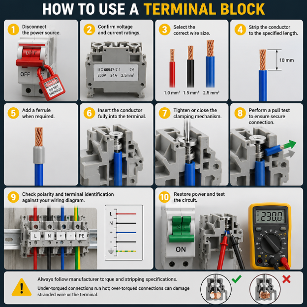
Here’s the process from start to finish:
- Disconnect the power source. Always work on de-energized circuits, and verify with a meter before touching any conductor.
- Confirm the terminal block voltage and current ratings against the actual circuit you’re connecting. Never assume; check the datasheet.
- Select the correct wire size based on the terminal’s rated wire range and the circuit’s current load.
- Strip the conductor to the specified length. Too short and you risk poor contact; too long and you risk exposed copper outside the terminal.
- Add a ferrule when required, particularly with stranded wire, to prevent fraying and ensure even clamping pressure.
- Insert the conductor fully into the terminal opening, making sure no insulation is trapped under the clamp.
- Tighten or close the clamping mechanism, following the manufacturer’s torque specification for screw terminals.
- Perform a pull test, gently tugging the wire to confirm it’s mechanically secure before moving on.
- Check polarity and terminal identification against your wiring diagram before energizing anything.
- Restore power and test the circuit under normal operating conditions.
A quick safety note: manufacturer torque and stripping specifications exist for a reason, and skipping them is the single most common root cause of terminal block failures we see referenced in field reports.
How to Wire a Terminal Block
The basic installation process stays similar across most terminal blocks. However, the wiring layout changes based on the circuit.
One-to-One Wire Connection
A one-to-one connection joins one incoming conductor to one outgoing conductor.
This is the simplest terminal block wiring method. It works well for point-to-point control wiring and field connections.
Power Distribution
When one supply needs to feed several circuits, installers use jumpers or distribution blocks.
These accessories bridge adjacent terminals and split one feed into multiple outputs. As a result, the panel stays cleaner than it would with several separate splices.
Grounding Connections
Protective-earth conductors connect to dedicated ground terminal blocks.
The terminal then bonds to a grounded DIN rail or earth bus. This connection forms part of the safety system, so it must match the grounding design of the panel.
Sensor and Control Wiring
PLC inputs, relay coils, switches, sensors, and low-voltage signals often use smaller terminal blocks.
In these circuits, wiring density matters more than current capacity. A single control cabinet may contain hundreds of low-current signal connections.
Three-Phase Connections
Three-phase wiring needs extra care.
You must identify each phase clearly, verify the current rating, and maintain safe spacing. In addition, you should use protective covers where exposed terminals could create a shock risk.
How to Select the Right Terminal Block
Choosing the right terminal block comes down to nine practical checks. Work through them in order, and you will avoid most selection mistakes.
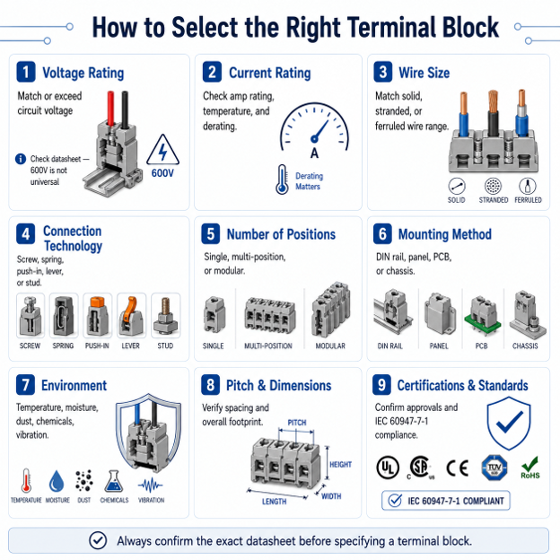
1. Determine the Voltage Rating
The terminal block voltage rating must meet or exceed the circuit voltage. It also needs enough safety margin for the installation.
This is where searches like terminal block 600V and 600V terminal block usually appear. However, a 600V rating is not a universal standard for every terminal block.
Instead, it is a manufacturer rating based on the terminal’s insulation material, spacing, certification, and test conditions. Therefore, check the datasheet for rated voltage, insulation voltage, surge voltage, pollution degree, creepage distance, and clearance distance.
Do not choose a terminal block only because the label says 600V. Confirm that the full rating matches the real environment.
2. Check the Current Rating
The terminal block current rating tells you how much continuous current the block can carry without overheating.
This rating depends on the current bar material, terminal size, wire gauge, ambient temperature, and enclosure ventilation.
For example, a terminal rated for 30A in a standard test environment may need derating in a hot control cabinet. Therefore, check the manufacturer’s derating curve when the circuit operates near the rated limit.
3. Match the Wire Size
Wire compatibility covers more than gauge.
- Solid wire: A rigid single-strand conductor, common in fixed panel wiring.
- Stranded wire: A flexible multi-strand conductor, common where movement or vibration may occur.
- Ferruled wire: Stranded wire fitted with a crimped ferrule to prevent fraying and improve clamping.
- Minimum and maximum conductor size: Every terminal has a defined wire range. If you go outside it, the connection may fail even if the wire appears to fit.
4. Select the Connection Technology
Choose the connection method based on the installation environment.
For example, screw terminals work well in many standard panels. However, spring-clamp and push-in terminals often perform better in vibration-prone systems. Stud terminals suit heavy-gauge, high-current wiring.
Also consider the tools your technicians use and how often they will service the wiring.
5. Consider the Number of Positions
Terminal blocks come in single-position, multi-position, and modular formats.
A fixed multi-position block works well when you know the circuit count. However, modular DIN rail terminal blocks make future expansion easier.
6. Choose the Mounting Method
The mounting method affects installation speed, panel layout, and serviceability.
- DIN rail mounting: Common in control cabinets. It is fast to install and easy to expand.
- Panel mounting: Uses screws to mount the block directly to an enclosure.
- PCB mounting: Solders the terminal block to a circuit board.
- Chassis mounting: Bolts the block to equipment chassis, often in heavier industrial systems.
7. Check Environmental Requirements
Consider the conditions the terminal block will face.
Check temperature, moisture, dust, chemicals, vibration, corrosion risk, and indoor or outdoor exposure. A block that works well in a clean panel room may fail early in a washdown area or outdoor enclosure.
Therefore, match the housing material, plating, and protection level to the environment.
8. Verify Pitch and Physical Dimensions
Pitch is the centre-to-centre spacing between terminal positions.
This matters most in compact equipment and PCB terminal blocks. Before ordering, check the pitch, footprint, height, and wire-entry direction against your board or panel layout.
9. Review Certifications and Standards
Check the manufacturer approvals and safety certifications for the exact part.
For industrial low-voltage switchgear, standards such as IEC 60947-7-1 cover terminal blocks for copper conductors. However, you should not assume compliance.
Terminal Block Materials
Terminal block materials affect safety, durability, current capacity, and environmental resistance.
Housing Materials
The housing must insulate live parts and withstand the operating environment.
- Polyamide, or nylon: Strong, heat-resistant, and common in general-purpose terminal blocks.
- Polycarbonate: Impact-resistant and useful where visual inspection matters.
- Thermoplastic blends: Designed for specific flame-retardance, heat, or chemical-resistance needs.
- Ceramic: Suitable for high-temperature applications where standard plastics would degrade.
Conductive Materials
The conductive parts carry current and maintain contact pressure.
- Copper alloys: Provide good conductivity and mechanical strength.
- Brass: Offers durability and easy machining, so manufacturers often use it in current bars and screw components.
- Tin-plated copper: Helps resist corrosion in humid or outdoor environments.
- Nickel-plated components: Improve contact durability and corrosion resistance in tougher conditions.
Plating slows oxidation and helps maintain low contact resistance over time. As a result, plated components often perform better in harsh environments than bare metal.
Terminal Block Maintenance and Troubleshooting
Routine inspection helps catch terminal block problems before they cause downtime.
Look for:
- Loose conductors
- Discoloration
- Heat damage
- Cracked housings
- Corrosion
- Burn marks
- Damaged labels
- Reduced clamping force
Start with a visual inspection. Then, perform a light pull test if the circuit is safe and de-energized.
Continuity testing confirms that the circuit remains intact. In addition, voltage-drop testing under load can reveal a high-resistance connection before it fails.
Thermal inspection also helps. An infrared thermometer or thermal camera can identify hot spots during normal operation.
Terminal Blocks vs Other Wire Connectors
Terminal blocks are not the only way to join wires. However, they offer strong advantages when you need organised and serviceable wiring.
Terminal Block vs Wire Nut
A wire nut twists conductors together and caps the joint.
It installs quickly, but it does not suit wiring that needs frequent changes. A terminal block, by contrast, lets technicians disconnect and reconnect wiring without cutting or re-splicing.
Terminal Block vs WAGO-Style Lever Connector
Lever-style connectors use a spring-clamp principle, much like lever terminal blocks.
However, most lever connectors work as standalone splice connectors. They suit junction boxes and quick field splices.
Terminal blocks work better in organised panel wiring because they support DIN rail mounting, markers, jumpers, and accessories.
Terminal Block vs Crimp Connector
A crimp connector creates a permanent mechanical joint by compressing metal around a conductor.
Crimps work well in compact and vibration-resistant applications. However, you cannot open them without cutting the wire. Terminal blocks are better when wiring needs service access.
Terminal Block vs Soldered Connection
Soldering creates a permanent low-resistance joint.
However, it takes more skill, adds time, and makes future changes harder. Terminal blocks trade some permanence for better serviceability, which makes them a better choice in many control panels and equipment assemblies.
In short, crimping and soldering suit permanent connections. Lever connectors suit quick splicing. Terminal blocks suit organised, labelled, serviceable wiring.
Final Thoughts
Terminal blocks may look simple, but the right choice affects wiring safety, reliability, and long-term maintenance. The best option depends on voltage and current ratings, wire size, connection method, mounting style, panel space, and operating environment.
DIN rail terminal blocks suit control cabinets and automation systems. Meanwhile, PCB, pluggable, barrier, fuse, disconnect, ground, and feed-through blocks each serve different wiring needs.
Before selecting a terminal block connector, always check the datasheet for rated voltage, current rating, wire range, pitch, torque, certifications, and compatible accessories.
Flywing Tech supplies a wide range of full terminal block catalogs across barrier blocks, DIN rail and channel mount, panel mount, power distribution blocks, and wire-to-board terminal blocks.
Browse the terminal block catalog or send an RFQ if you need help matching a part to your exact requirements.
Frequently Asked Questions
What is a terminal block used for?
A terminal block connects, organises, and distributes electrical wiring at a serviceable junction point. It lets technicians connect wires without soldering or permanent splicing.
How do terminal blocks work?
Terminal blocks clamp a conductor against a conductive metal bar. The bar carries current between connected terminals, while the housing insulates and protects the connection.
Can you connect multiple wires to one terminal block?
Some terminal blocks allow multiple wires per position. However, you must check the manufacturer’s limit first. Too many wires can reduce clamping pressure and create a loose connection.
Do terminal blocks need ferrules?
Ferrules are not always required. However, they help with stranded wire because they prevent fraying and improve clamping consistency.
What is the difference between a terminal block and a terminal strip?
A terminal block is usually an individual or modular connection point. A terminal strip usually contains several terminals fixed together on one base.
What are DIN rail terminal blocks?
DIN rail terminal blocks snap onto a standard metal DIN rail. They are common in control cabinets, automation systems, distribution boards, and industrial enclosures.
Can terminal blocks be used for high-voltage wiring?
Yes, some terminal blocks support higher-voltage wiring. However, you must check the rated voltage, insulation voltage, pollution degree, creepage, clearance, and certification before use.
What does a 600V terminal block rating mean?
A 600V terminal block rating means the manufacturer rated that specific part for operation up to 600V under defined conditions. It does not mean every 600V circuit is automatically safe for that block.
Can stranded wire be used in a terminal block?
Yes, most terminal blocks accept stranded wire. However, spring-clamp and push-in designs often work best with ferruled stranded wire.
How tight should a screw terminal block be?
Tighten a screw terminal block to the manufacturer’s specified torque. Do not rely on feel. Under-tightening can cause heat, while over-tightening can damage the conductor or housing.
COMMENTS