The AS5600 magnetic encoder is a 12-bit contactless angular position sensor. It is developed by ams OSRAM, with a planar Hall effect sensing architecture. The AS5600 magnetic encoder detects the position of an external permanent magnet that rotates above the sensor; optical and mechanical encoders both contact the encoder. The absolute position output provides a full 360° range of measurement, and can be read using the three communication modes. I2C, analog voltage and PWM all in a compact SOIC-8 package, with a power supply between 3.3V to 5V.
The IC was designed specifically to replace mechanical potentiometers in applications. That require long life and resistance to vibration, dirt or moisture. Mechanical potentiometers are physically worn through their debris at the contact points between the wiper and the resistive element. Whereas, the AS5600 uses a solid-state, non-contact magnetic field measurement system to determine the position. Therefore the AS5600 is the ideal solution for applications such as motor shaft feedback, robotic joint sensing, and panels. The knobs that require absolute position information without the failure modes of contact-based sensors.
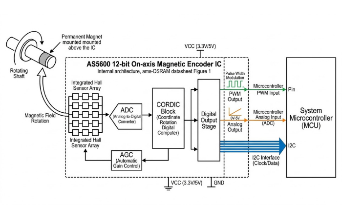
The AS5600 magnetic rotary encoder utilizes a fixed wiring CORDIC algorithm. To calculate the angle of the magnetic field vector from the raw Hall signal with a resolution of 12 bits. There are 4096 unique positions for each rotation of the encoder. So, the increment value for each position is 0.087 degrees. The Automatic Gain Control loop continuously monitors temperature, magnet wear, and changing distance between the magnet and IC surface and maintains proper amplifier gain under all conditions. This produces a stable, self-correcting angle output that does not need periodic recalibration during its operational life.
What Is the AS5600? Technical Overview and Design Architecture
The AS5600 is a non-contact absolute rotary position sensor developed by ams OSRAM, using Hall Effect magnetic sensing technology. It measures the angular position of a magnet suspended above the IC and outputs a digital value between 0 and 4095. In contrast to contact type position sensors, there is no mechanical interface between the magnet and the AS5600. As a result, the absence of continuous contact, eliminates failure modes associated with mechanical wear, improving overall reliability.
The AS5600 magnetic encoder differs greatly from standard Hall effect switches and standard linear Hall sensors with an onboard complete signal processing pipeline. The AS5600 does not externally output raw differential Hall signals to the host processor for the calculation of angle. The CORDIC block in the AS5600 internally performs the total arctangent calculations and directly outputs a final 12-bit angle measurement. Therefore, the host microcontroller receives an already processed angle measurement as opposed to unprocessed raw sensor data. That would have required trigonometric calculations.
Hall Effect Sensing Principle in the AS5600
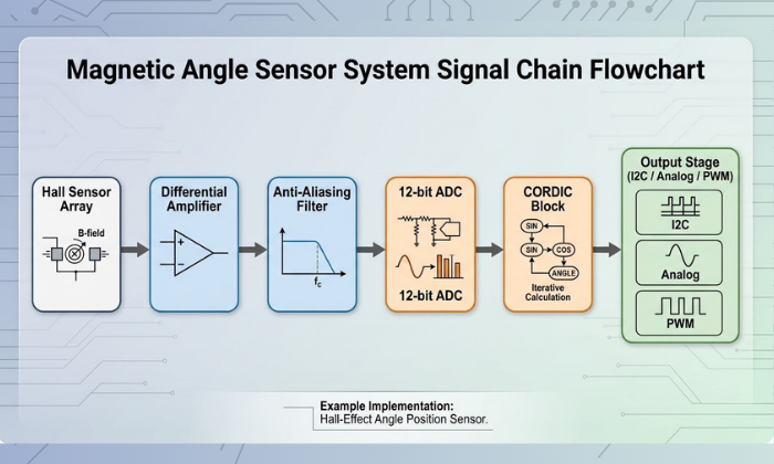
The AS5600 utilizes a series of planar Hall sensor elements, which are embedded in the silicon surface of the integrated circuit chip. Planar Hall sensors are designed to detect a very specific aspect of a magnetic field. Namely the vertical magnetic field component, or Bz, which is perpendicular to the chip surface. As a diametrically magnetized magnet is rotated above the integrated circuit chip. So, is the direction of this perpendicular magnetic field component, sweeping 360 degrees with each mechanical revolution.
The planar Hall sensor array simultaneously detects two orthogonal Hall channels. Which equates to measuring the X and Y axes of a rotating magnetic field vector in a planar surface. These two differential signals then pass through a low noise amplifier and an analog anti-alias filter prior to entering the ADC inputs. This is an important stage in the overall system, as Hall voltage signals are typically in the microvolt to millivolts. It must be amplified significantly in order to be accurately converted to a 12-bit level by an ADC.
It is important to understand that the AS5600 does not actually measure. The magnetic field strength to determine the angle, but rather the direction of the magnetic field. This distinction has a direct practical consequence: moderate variation in field strength. It caused by temperature change magnet aging, and gap variation. The direction will not be affected, and hence the angle will not be affected. The AGC loop, described below, handles the magnitude variation so the CORDIC block always receives signals of consistent amplitude.
CORDIC Block and Angle Computation Pipeline
After being amplified, filtered, and digitized by the 12-bit ADC. The Hall channel signals enter the hardwired CORDIC block (Coordinate Rotation Digital Computer). The CORDIC algorithm calculates the arctangent of the ratio of the two ADC outputs. To determine the angle of the magnetic field vector in the XY plane.
This calculation produces a 12-bit angle value representing the magnet’s rotational position, with 4096 counts per full rotation.
The complete signal processing pipeline from sensing to output is as follows:
The CORDIC algorithm implemented within the AS5600 is hardwired, i.e., it is not a software algorithm executed by a processor. This gives rise to two major consequences. One consequence is that there is no variability in terms of computation time. There are no delays associated with instruction cycle times or interrupt response times. A second consequence is that there is no need for any computation on the part of the host microcontroller. This is because it simply reads a 12-bit result from the ANGLE register via I2C. This makes AS5600 particularly suitable when a deterministic response from a sensor is a hard requirement in a real-time control loop of a motor.
The output from the CORDIC algorithm is subsequently passed through a digital filter stage before being stored in the output register. The slow filter bits SF within the CONF register, along with fast filter threshold bits FTH, control the trade-off between output noise and angle step response time.
Automatic Gain Control (AGC) and Magnetic Field Compensation
A variable-gain amplifier, controlled by the Automatic Gain Control (AGC) loop, amplifies the Hall signal before it reaches the ADC. The AGC measures the magnitude of the 3-D magnetic field vector. From the combined amplitude of the two Hall channels and adjusts the gain of the amplifier. To maintain a constant signal level at the ADC input, regardless of variations in magnetic field strength.
This compensation mechanism addresses three physical sources of magnetic field variation that would otherwise degrade angle accuracy:
Temperature drift
NdFeB magnets will lose approximately 0.1% of their permanent magnetic strength. For every degree Celsius that temperature increases (in this case from -40° to +125°C). It resulting in a maximum reduction of approximately 16.5% in field strength at the upper temperature limit. The AGC is capable of automatically compensating for this decrease in field strength by increasing gain. Which counteracts the fall-off of the magnetic field near the operating temperature.
Magnet aging
Permanent magnets will be subject to long-term (months to years) demagnetization. If they are not maintained or if they experience excessive heat or mechanical shock during this time. Through the AGC loop’s ability to maintain appropriate gain. As the magnetic assembly slowly falls out of specification due to time, temperature and shock. The AGC will effectively extend the useful life of the magnetic assembly.
Air gap variation
In environments where the shaft assembly will undergo continual thermal expansion or where it is subject to mechanical vibration. The distance between the magnet and the surface of the Integrated Circuit (IC) will change. The strength of the magnetic field will decrease very rapidly as distance from the magnet. It increases (approximately by the cube of the distance from magnet for a point dipole). Therefore, even small changes in the distance between magnets can have significant effects on field strength. The AGC will compensate for this distance change without requiring any firmware changes.
The current AGC gain setting may be read at any time from the 8-bit AGC register (address 0x1A). This ranges from 0 (minimum gain, strongest field) to 255 (maximum gain, weakest field). During mechanical assembly and alignment, this register is used as a primary diagnostic tool. A reading close to mid-range (around 128) indicates that the magnet is within the optimal range of field strength. Readings close to 0 or 255 suggest that the field strength is too strong or too weak, respectively. Hence the air gap needs adjustment.
The STATUS register (address 0x0B) contains three flags which provide diagnostic output based on the AGC state. MD (Magnet Detected) must be set to a logic 1 to enable output. MH (Magnet too strong, High) is asserted when the AGC has reached its minimum gain limit. Similarly, ML (Magnet too weak, Low) is asserted when the AGC has reached its maximum gain limit. But the field remains too weak—i.e., below 8 mT—upon which output is disabled, and the ANGLE reading becomes invalid.
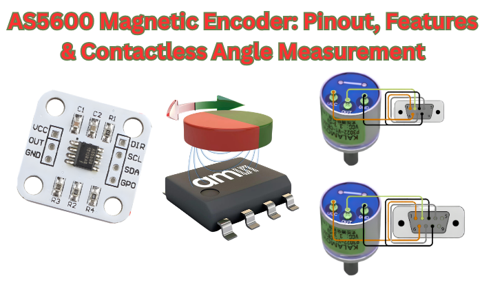
AS5600 Pinout — Pin Descriptions and Electrical Characteristics

The AS5600 device comes in an 8-pin SOIC package, known as the SOIC-8. The pins are grouped in three categories: power, I2C communication, and output. It is important to fully understand the purpose and electrical specifications for all pins before the development of a PCB. It is also important to note that two pins, PGO and OUT, are related in a way that may not be immediately obvious from the name and are a major contributor to many hardware integration failures in third-party breakout modules.
The eight pins on the AS5600 are VDD, GND, SCL, SDA, DIR, OUT, PGO, and NC. A full description of all pins is given below.
Power Supply Pins — VDD and GND
The AS5600 offers two voltage supply ranges, depending on the logic level of the system in which it is integrated. For 3.3 V logic level, VDD should be maintained between 3.0 V and 3.6 V, while for 5 V logic level. It should be maintained between 4.5 V and 5.5 V. Operation outside this voltage supply range is undefined and might lead to inaccuracy in the output and possible permanent damage to the device. It is noteworthy that this device does not have an in-built voltage regulator, and therefore, a clean and stable voltage supply rail should be ensured before a valid output is produced by this device.
In normal operation with the output stage enabled, this device draws a current of 6.5 mA from VDD. This is a considerable current and should be considered in addition to other currents, such as those from I2C pull-up resistors, in a system where this device is integrated, especially in a system where power is supplied by a battery. This current is reduced to 0.5 mA in LPM3, with a possible increase in angle update latency to 100 ms.
Decoupling capacitor
A 100nF ceramic decoupling capacitor needs to be placed between VDD and GND, as close as technically feasible to the VDD pin on the PCB. This is not optional but a stringent requirement based on the ams OSRAM application note. This high-frequency switching noise on the supply rail directly affects the microvolt-level Hall sensor signals before reaching the amplifier stage. In cases where the AS5600 IC is placed close to a switching regulator or a PWM-controlled motor driver, a 10 µF bulk capacitor in parallel to the 100nF capacitor is strongly recommended to reduce low-frequency ripple effects.
The GND pin needs to be connected directly to the system ground plane. A floating ground connection is a typical reason for erratic angle output, which cannot be easily debugged unless a current measurement of the power supply is performed.
I2C Communication Pins — SDA and SCL
The SDA and SCL pins provide a standard I2C interface. The AS5600 device only functions as an I2C slave and never acts as an I2C master. The I2C interface can be configured to support both standard mode at 100 kHz and fast mode at 400 kHz. The device does not support fast mode plus at 1 MHz or high-speed mode at 3.4 MHz.
One key constraint in the design of the magnetic encoder in the AS5600 device is that the I2C address is permanently fixed at 0x36 and can never be changed by any software or hardware configuration. There are no address select pins, and there are no address bits to set. There is also no ability to change the I2C addresses at the register level. This effectively means that there can be only one AS5600 device on any given I2C bus. If two AS5600 devices are placed on the same I2C bus by connecting their SDA and SCL pins to the same I2C pins, then there will be contention on the I2C bus. This results in both devices having non-functional behavior.
Multiple AS5600 sensors
For a design that requires multiple AS5600 sensors, such as a multi-axis robotic arm or a multi-motor system using a FOC approach, the architectural solution is the use of an I2C multiplexer. The two most common ICs for this application are the TCA9548A (8-channel) and PCA9548A. Each AS5600 is connected to a separate channel on the multiplexer and addressed in the same way as described above: first select the appropriate channel on the multiplexer and then send the standard 0x36 address transaction.
For SDA and SCL, external pull-up resistors to VDD are required. These are non-optional; without them, the open-drain lines for the I2C bus will float, and the bus will not function. The recommended value for these resistors is 4.7 kΩ for a 5V system and 2.2 kΩ for a 3.3V system. If significantly higher values (for example, 10 kΩ) are used for the pull-up resistors, the rise time on the bus lines increases, which can prevent communication at 400 kHz. A significant number of AS5600 breakout board modules already have these resistors included; make sure this is the case before adding external ones, as this can stress the I2C output drivers on the microcontroller board.
DIR Pin — Rotation Direction Control
The DIR (Direction) pin controls the polarity of the angle count relative to the physical rotation direction of the magnet. Its function is simple and binary:
- DIR connected to GND → angle value increases with clockwise rotation (when viewed from the magnet side, looking down toward the IC)
- DIR connected to VDD → angle value increases with counterclockwise rotation
This is a hardwired polarity reversal, and it is performed entirely in the output stage of the AS5600. This is not a software register bit and does not require any firmware modifications to enable this feature. It is important to note that the DIR pin must be driven to a valid logic level, either GND or VDD, and should not be left floating, as this will cause undefined rotation polarity operation.
The significance of this pin becomes apparent in a mechanical context. When the AS5600 is mounted to the underside of a PCB with the magnet located above, or if the sensor is facing to the rear of a rotating shaft rather than to the front, the apparent direction of rotation, as sensed by the IC, is physically reversed with respect to the mechanical system’s reference frame. Instead of addressing this in software by performing a subtraction operation during every reading of the angle, this DIR pin allows the reference frame to be corrected in hardware with a single change to a solder connection.
OUT Pin — Analog, PWM, and Output Mode Selection
The OUT pin is the analog and PWM output terminal of the AS5600. Its behavior is determined by the OUTS[1:0] bits in the CONF register (address 0x07–0x08), which select one of three output configurations:
- OUTS = 00 → Analog output, full range (approximately 10% VDD to 90% VDD across 0°–360°)
- OUTS = 01 → Analog output, reduced range (approximately 10% VDD to 90% VDD across the programmed ZPOS–MPOS sub-range)
- OUTS = 10 → PWM output (duty cycle proportional to angle, frequency set by PWMF bits)
If the I2C digital output is used as the principal data path, the OUT pin need not be connected; however, the CONF register must be set correctly, as an incorrectly set output stage can load the OUT pin in ways that are not anticipated.
There is a significant interdependency between the OUT pin and the PGO pin during the execution of the programming sequences for OTP programming. If the PGO pin is set low and a BURN command is executed, the OUT pin takes on a programming interface function and must not be loaded during this period. The OUT pin is disabled as an analog/PWM output on breakout modules that connect the PGO pin to ground; this is a hardware conflict that renders the output completely unusable. This subject is covered in more detail in the section on the PGO pin that immediately follows this section..
PGO Pin — OTP Programming Interface
The PGO (Programming Option) pin selects the programming interface mode of the AS5600 at power-up. Its state during the power-on reset sequence determines how the device accepts configuration data:
- PGO floating or connected to VDD → standard I2C programming mode (default for most applications)
- PGO connected to GND → 3-wire programming mode, which uses the OUT pin as a programming pulse input
The majority of I2C usage for both data retrieval and configuration will see PGO left unconnected (floating) or connected to VDD via a 10 kΩ resistor. Connecting PGO to GND will enable 3-wire mode, where the OUT pin will be dedicated to the reception of programming pulses and will be disabled as an analog/PWM output.
This is a well-documented hardware problem with many low-cost breakout modules for the AS5600 from various third-party suppliers. Some of these breakout boards are shipped with a 0Ω jumper resistor connected to GND, or, in other cases, a direct solder bridge is present between the PGO pin and GND, intended to enable 3-wire programming out of the box. The consequence is that the OUT pin will not provide analog/PWM output, irrespective of CONF Register settings, because it is always in 3-wire mode. The solution is to remove the jumper resistor using a soldering iron and flux. The RobTillaart AS5600 Arduino library README section documents this problem and states that it is the most common cause of OUT pin failure.
If your application really needs to use 3-wire programming, i.e., calibration in the field without I2C programmer, then the PGO pin should be connected to GND during the programming sequence and then disconnected (or connected to VDD) when not programming. A simple solution is to use a small MOSFET and analog switch controlled from a GPIO pin.

AS5600 Key Electrical and Performance Specifications
Before incorporating the AS5600 magnetic encoder into any hardware project, the specifications need to be checked against the needs of the intended application. The parameters listed here are taken from the ams OSRAM AS5600 datasheet and represent the entire operating range of this magnetic encoder IC, from supply voltage and current draw to resolution and accuracy in angle measurement and temperature range. Where a specification has direct implications for the design, this is made obvious rather than left open to interpretation.
Supply Voltage and Absolute Maximum Ratings
The AS5600 works with a single supply rail and is qualified with two voltage window specifications: 3.0 V to 3.6 V for 3.3 V supply voltage systems and 4.5 V to 5.5 V for 5 V supply voltage systems. There is no LDO or voltage regulator on chip, and the supply voltage is directly applied to the analog front end. Operating with a supply voltage between 3.6 V and 4.5 V is explicitly outside of the valid supply voltage range and places the device in an undefined state where accuracy of the measurements is not ensured and output behavior is unpredictable.
The absolute maximum voltage on VDD is 7 V. Operation above 5.5 V is not sustainable and will destroy the device, but a voltage transient between 5.5 V and 7 V during a hot swap or power sequencing event will not immediately cause a failure. The absolute maximum voltage on any of the signal pins (SDA, SCL, DIR, OUT, PGO) is VDD + 0.3 V. Applying 5 V logic signals to any of these pins while running on a 3.3 V supply voltage is above this level and could cause latch-up or damage to the pins. This is an important consideration in an application where a 3.3 V supply voltage version of the AS5600 is to be used with a 5 V supply voltage version of an Arduino.
Angular Resolution and Measurement Accuracy
The AS5600 magnetic encoder produces a 12-bit angle output, corresponding to 4096 discrete positions per full 360° revolution. This gives an angular resolution of:
This resolution figure indicates the finest angular increment that the device is able to represent in its output register; it does not imply any form of accuracy. Resolution and accuracy are different parameters that should not be confused with one another.
The angular accuracy figure for the AS5600 is a maximum deviation between the actual angle reported and the true mechanical angle. This figure is rated at ±0.5° typical under optimal conditions: using the correct type of magnet, with the magnet centered in the magnetic field, with the AGC value near the midpoint of its range, and with the operating temperature within the 25°C ±10°C band. When using the AS5600 under worst-case conditions, with the full operating temperature range and with non-ideal magnet alignment, the angular accuracy figure suffers accordingly. According to the ams OSRAM data sheet for the AS5600, the integral non-linearity (INL) is rated at ±0.5° typical, ±1.0° maximum over the full operating temperature range.
For context’s sake, the AS5600’s accuracy performance places it well above that which is possible with a standard 10-bit potentiometer-based ADC system (where non-linearity, contact noise, and drift are also a problem), while still keeping it below the 14-bit AS5048 family for those applications where sub-0.02° accuracy is a requirement.
The MAGNITUDE register (0x1B–0x1C) holds information related to the magnitude of the magnetic field vector that is being sensed. This information is useful during commissioning to verify that the magnet and sensor are properly aligned; a non-zero magnitude reading near the midpoint of the AGC’s operating window should yield the best possible accuracy.
Output Noise and Dynamic Response
The AS5600 includes a configurable digital filter applied to the output of the CORDIC. The filter determines the trade off between output and response time to angular changes.Both filtering mechanisms are controlled through the CONF register.
The slow filter (SF[1:0] bits) consists of a fixed averaging filter and may be set to one of four possible oversampling ratios. The oversampling ratios are: 16x, 8x, 4x, and 2x. The use of higher oversampling ratios will yield less noise in the output at the expense of longer latency. The typical output update rate for an output sampled at 16x in normal mode will be approximately 14.7Hz.
This is sufficiently low to indicate an approximate motor’s position but is not fast enough to provide feedback for commutation of a motor spinning at anything greater than a few RPM. Conversely, an output sampled at 2X would update at approximately at 116Hz which would be adequate for light motor control applications.
The threshold of the fast filter (FTH[2:0] bits) function as a method of detecting a step: if the angular distance between two consecutive samples exceeds the value programmed into this field, then the filter will switch to fast (unfiltered) mode for that sample to accommodate the rapid movement occurring between samples, and then switch back to slow filter mode.
This enables the output to be a low noise steady-state output during the time that there is no change in position and to respond rapidly to any commanded position change during the time of travelling to the commanded position.
As a general rule: use maximum oversampling (16x slow filter) for slow knob/panel controls, use 2x slow filter with fast filter threshold enabled for motor commutation feedback, and use normal mode with minimal filtering for high-speed shaft angle measurement.
Operating Temperature Range and Thermal Derating
The AS5600 is specified across an operating temperature range of −40°C to +125°C, covering the full industrial and automotive temperature range with the exception of the extended automotive AEC-Q100 Grade 0 requirement of −40°C to +150°C (which the AS5048 family covers). For most industrial, consumer, and maker applications, the +125°C upper limit is not a binding constraint.
Within this temperature range, two temperature-dependent effects are relevant to system accuracy:
Magnet remanence temperature coefficient
As noted in the AGC section, NdFeB magnets lose field strength at approximately 0.1% / °C. While there is AGC loop compensation for this loss of strength, the level of compensation is inconsistent at the end of the AGC gain range. If the magnet is positioned at or near the edge of field strength range (i.e., AGC position near 0 or 255) and is exposed to temperature changes, the resulting variation in field strength may result in the AGC going above or below valid operating limits, causing the MH or ML status flags to be set, and hence the output will be disabled.
IC offset drift
Both the Hall-element and amplifier chain have some residual offset that changes as the temperature changes. Therefore, this is also the cause for the accuracy loss at high and low-temperature extremes, as specified in the ±1.0° maximum accuracy specification above. For applications that are continuously operating above 85°C, it is recommended to verify the angle accuracy at the maximum temperature of operation during system validation instead of only relying on the accuracy at room temperature.
The SOIC-8 package has a thermal resistance (θJA) of approximately 100°C/W in still air. At 6.5 mA from a 5V supply, the AS5600 dissipates approximately 32.5 mW in normal mode — producing a junction temperature rise of only ~3°C above ambient. Self-heating is therefore not a meaningful accuracy concern under normal operating conditions.
Current Consumption and Power Mode Summary
Current consumption figures are for VDD = 5V with I2C output mode active. Analog and PWM output modes draw marginally higher current due to the active output driver stage. In all low power modes, the device automatically enters a sleep state between measurement cycles — no firmware command is required to initiate sleep, and the device wakes autonomously at the programmed polling interval.
AS5600 Output Modes: Analog, PWM, and I2C Digital
The AS5600 magnetic encoder offers multiple output formats (modes) which are selected through two configuration bits (OUTS[1:0]) in the configuration register; these output formats are analog voltage, Pulse Width Modulation (PWM), and I2C digital. Each output format uses a different physical output path to the host system and has different impact on wiring, noise immunity, complexity of interfacing to the microcontroller, and the speed at which the output data is updated. The correct output format to use for an application is determined by the installation of the application, and not necessarily by which output format will be easiest to implement.
All three output formats use the same underlying 12-bit angular value created by the CORDIC block, however, they present that angular value in different ways to the host system; the angular value can be outputted as an analog voltage level at the OUT pin, by a PWM output from the OUT pin, or as an 8 or 16-bit register value available on the I2C bus. Choosing the wrong output format for an application, particularly confusing the analog and PWM formats, is one of the most common causes of integration errors which cause the angle readings to appear random or non-linear.
Analog Output Mode
When the OUT pin operates in analog output mode, it generates a DC voltage that is linear and directly proportional to the angular position within the configured angular range. The simplest implementation uses a microcontroller ADC, requiring no register access, with rotation represented by a single voltage trace.
The analog output does not cover the whole VDD rail. For a 360° angular range, the output voltage will go from approximately 10% of VDD at 0° to about 90% of VDD at 360°. For a 3.3V system, this gives an output voltage of approximately 0.33V to approximately 2.97V. Similarly, for a 5V supply, the output voltage will be approximately 0.5V to 4.5V. The output stays below the supply rails to prevent saturation, so the host ADC must handle less-than-full-scale voltage.
When ZPOS and MPOS limit the angle to less than 360°, the analog output spans 10%–90% VDD across that sub-range.
DAC resolution Formula
The DAC resolution available for the sub-range is proportionally reduced:
In the case of a 90-degree programmed range, the number of effective steps across the output window would thus be 1024 which would be the equivalent to 10 bits of resolution from a D/A converter. In the case of a 180-degree programmed range, the number of steps would thus be 2048 which would be the equivalent to 11 bits of resolution from a D/A converter. Consider the resolution reduction when using the AS5600 as a contactless potentiometer for limited-angle applications.
Use analog output mode when the host has ADC channels, wiring is under 30 cm, and diagnostic data via I2C is not needed. For long cables or noisy environments, PWM output mode provides better noise immunity.
PWM Output Mode
In PWM output mode, the OUT pin produces a pulse-width modulated signal whose duty cycle is linearly proportional to the measured angle across the programmed range. PWM encodes angle in time, making it more resistant to DC offset, supply noise, and resistive losses than analog voltage.
PWMF[1:0] bits in the CONF register
Set the PWM carrier frequency using the PWMF[1:0] bits in the CONF register, offering four options.
The default frequency is 115 Hz, with duty cycle from 0.5% to 99.5%, ensuring measurable pulses at both angle endpoints.
On the host microcontroller side, PWM input capture is required to decode the angle from the duty cycle. Most microcontrollers with hardware timer input capture peripherals — including all Arduino-compatible boards with ATmega328P, ESP32, or STM32 processors — can perform this measurement natively. The angle in degrees is computed as:
The OUT pin also serves as the programming pulse input when used in the 3- wire mode. IIn PWM mode, if PGO is grounded, three-wire programming takes priority and disables the PWM output. This isthe same hardware conflict described previously in the PGO pin section, therefore testing for the correct state of the PGO pin is the first step in diagnostics if the PWM output is not present or exhibits unusual behavior.
Use PWM output when signals must travel over 30 cm, near switching supplies, or when I²C bus complexity is an issue.
I2C Register Map and Digital Angle Reading
The AS5600 magnetic encoder has its most information-rich output through the I2C digital interface (compared to the outputs available via the Analog and PWM modes of output which only provide an angle value). The I2C output provides the full internal state of the device which includes: raw angle, filtered angle, magnetic field magnitude, AGC gain value, configuration registers and diagnostic status flags. I2C is required for applications needing magnet alignment diagnostics, output configuration, or OTP programming.
The AS5600 I2C register map is organized into read-only output registers and read/write configuration registers. The key registers for normal operation are:
The registers relevant to angle reading and system diagnostics are:
RAW ANGLE register (0x0C–0x0D)
The 12-bit angle value directly from the CORDIC output, before the digital filter stage. This is the lowest-latency angle reading available from the device. The value updates at the full ADC sampling rate regardless of the slow filter setting. Use RAW ANGLE when minimum latency is more important than noise reduction — for example, in fast motor commutation loops.
ANGLE register (0x0E–0x0F)
The 12-bit angle value after the digital filter stage configured by the SF and FTH bits in CONF. This is the primary angle output for most applications. The value is smoother than RAW ANGLE but has higher latency at high oversampling ratios. For most position sensing and potentiometer replacement applications, ANGLE is the correct register to read.
STATUS register (0x0B)
A single byte containing three diagnostic flag bits: MD (bit 5), ML (bit 4), and MH (bit 3). MD must be 1 for any angle reading to be valid. Reading the STATUS register should be the first operation in any initialization sequence — proceeding to read ANGLE without first confirming MD = 1 risks storing an invalid angle value as a valid position reference.
MAGNITUDE register (0x1B–0x1C)
The 12-bit magnitude of the magnetic field vector, representing the combined amplitude of both Hall channels after AGC processing. This value helps optimize magnet placement during assembly and monitors magnet health during long-term operation.
AGC register (0x1A)
The current 8-bit gain value of the automatic gain control amplifier. As described in the architecture section, values near 128 indicate optimal magnetic field strength. Values near 0 or 255 indicate the field is at the edge of the AGC operating range.
CONF register (0x07–0x08)
The primary configuration register controlling power mode, output type, hysteresis, filter settings, PWM frequency, and watchdog enable. This register is covered in full detail in the CONF Register Deep Dive section.
Reading a 12-bit value from either the RAW ANGLE or ANGLE register requires a two-byte I2C read sequence from consecutive register addresses. The device uses a split-byte format: the high byte (lower address) contains the upper 4 bits of the 12-bit value in bits [3:0], with bits [7:4] unused and read as zero. The low byte (higher address) contains the lower 8 bits of the 12-bit value. The full 12-bit result is assembled as:
This two-byte assembly step is a common source of incorrect angle readings in custom I2C implementations. Reading only the low byte produces an 8-bit value that loses the upper 4 bits of angular resolution, reducing effective resolution from 12-bit (4096 counts) to 8-bit (256 counts) and introducing a systematic wraparound error every 90° of rotation. Always read both bytes in a single I2C transaction using a repeated start or sequential read to ensure the two bytes are coherent samples from the same conversion cycle.
Magnet Selection and Physical Mounting for Accurate Angle Measurement
The AS5600 magnetic encoder relies on the magnetic assembly above it to determine its accuracy. The IC, including CORDIC, AGC, and 12-bit ADC, achieves ±0.5° accuracy under ideal conditions, depending on magnet type, vertical air gap, and lateral centering. A misaligned or incorrect magnet cannot be corrected by software, filtering, or calibration.
This section outlines precisely and directly each of these three physical limits as they pertain to successful AS5600 integration. Integration fails with an AS5600 using the wrong magnet, showing a non-linear angle output often misdiagnosed as a firmware or configuration issue.
Diametric vs. Axial Magnetization — Why It Matters
Diametric Magnetization
The AS5600 requires a diametrically magnetized two-pole permanent magnet, also called diagonal or radial. A diametrically magnetized cylinder has north & south poles located on opposite edges of the rounded exterior; the magnetization vector runs horizontally across the diameter and perpendicularly to the centerline of the cylinder.
This differs from an axially magnetized disc, where the north and south poles are on opposite faces and the magnetization runs along the cylinder axis. Axially magnetized disc-type magnets are the most readily available type of magnet from common electronics supply and hobby stores, making this type of magnet the most often purchased incorrect type for this application.
Axial Magnetization
Rotating an axially magnetized magnet over the AS5600 keeps the perpendicular field (Bz) constant, not rotating with the magnet.
Both Hall channels then produce similar slow signals, not 90° phase-shifted sinusoids, causing stuck, jumping, or highly non-linear angle output. As a result, the STATUS register will normally show that MD = 1 (magnet detected because the field strength is sufficient) while the ANGLE register generates garbage data, making it easy to confuse as a firmware or I2C issue.
With the correct diametrically magnetized magnet in place, the perpendicular Bz component seen by the IC rotates in exact synchrony with the physical magnet rotation. As the magnet completes one full mechanical revolution, the magnetic field vector at the IC surface completes one full 360° electrical cycle. The two orthogonal Hall channels generate sinusoidal quadrature signals, and the CORDIC block outputs a linear angle across 360°.
Recommended magnet specifications for the AS5600:
Do not use ferrite magnets with the AS5600; their weaker, temperature-sensitive fields may fail to meet the 8 mT minimum. Use NdFeB N35 or N42 magnets, 4–6 mm diameter, diametrically magnetized as recommended by ams OSRAM and suppliers.
Vertical Air Gap, Centering Tolerance, and Field Strength Requirements
With the correct magnet type confirmed, the mechanical assembly must position that magnet within a precise spatial envelope above the AS5600 IC surface. Three geometric parameters govern the quality of the magnetic coupling between the magnet and the sensor: vertical air gap, lateral centering, and tilt angle.
Vertical Air Gap
Maintain the vertical distance between the magnet’s bottom and the AS5600 IC top surface at 0.5–3 mm. This range is not arbitrary — it defines the window within which the magnetic field strength at the Hall sensor array falls within the AGC’s compensation range.
The field is generally too strong when the gap is less than 0.5 mm. AGC gain reaches minimum, MH flag sets, and output may saturate or become non-linear near ADC full-scale limits. At gaps over 3 mm, field strength drops below 8 mT; AGC gain maxes, ML flag sets, and ANGLE output disables. The optimal distance for a standard 6 mm diameter N42 NdFeB diametric magnet target is approximately 1.0 mm to 1.5 mm, typically creating an AGC register value of 100-150 (about mid-scale/128).
In practice, the air gap includes the thickness of the PCB soldermask, conformal coating, or a protective cover over the IC, plus the mechanical tolerances in the shaft and bearing assembly. Consider stack-up tolerances in design to keep the air gap within 0.5–3 mm despite manufacturing and thermal variations.
Lateral Centering
To provide reliable angle output from the AS5600 integrated circuit (IC), it is critical to align the center of the magnet’s rotation axis with the center of the IC located within the SOIC-8 physical package (i.e., under the black plastic cover of the IC). Misalignment between the IC and magnet axis causes systematic errors that require full characterization and testing to correct.
The maximum allowed tolerance for accuracy as specified in the ams OSRAM Application Note is ±0.25mm; any misalignment beyond this tolerance will result in additional harmonic distortion in the signals from the Hall channels and therefore will cause the output angle to be further from the true angle. To meet this tolerance, use a precision-machined magnet holder or a self-centering magnetic assembly.
Tilt Angle
The magnet must rotate at right angles to the IC surface, positioned without any tilt relative to the chip.Tilt causes asymmetrical fields across the Hall sensor array, which the AGC and CORDIC cannot fully correct. In actual use, tilts of less than 1° will cause no noticeable loss of accuracy, while tilt angles between 3° – 6° will introduce significant harmonic deviations to the angle output. The predominant cause of effective tilt in typical designs is due to the run-out of the shaft in the bearing assembly.
Using the AGC Register as an Assembly Diagnostic
During mechanical assembly and alignment, the AGC register provides real-time feedback on the quality of the magnetic coupling without requiring any additional test equipment. The recommended assembly procedure is:
- Install a magnet in the intended location and apply power to the AS5600
- Check the STATUS register to ensure MD = 1, MH=0, ML=0
- Read the AGC register (address 0x1A)
- Rotate the shaft through one full revolution of 360°, logged as you do so in the ANGLE register. Verify that the output count from the ANGLE register goes in a single increment from 0-4095 and wraps correctly.
- Look for places around the complete rotation where either the ANGLE register value jumps, stops, or goes backwards. These locations require mechanical adjustments. Due to lateral misalignment or tilt of the magnet.
This six-step procedure requires only an I2C connection to a microcontroller running a simple register. No specialized magnetic field measurement equipment is needed for the read loop. The AGC register is the most practical alignment tool available during production assembly and field installation alike.
Field Strength Verification Without Test Equipment
Read the MD, MH, and ML flags from either the analog or PWM output. Zero voltage or missing pulses indicate below ML; full-scale suggests saturation at MH.
This method confirms field strength is below MH but is less precise than reading the AGC register, using only a voltmeter or oscilloscope.
Programming the AS5600 — Zero Position, Angle Range, and OTP Burn
The AS5600 encoder is factory programmed to map 0°–360° to an active position and set zero at the magnet’s default north. In certain situations, for example, when using a whole-surface shaft encoder that rotates through an entire electrical cycle or when using a motor position sensor, the encoder will work with no further adjustments to the programming.
However, if an application has limited movements (for example, a 270° knob, a 90° actuator, or a joystick that only moves a set distance) and/or the user would like the zero point of the output to correspond to a specific mechanical point instead of the arbitrary “default” north magnetic reference, then the AS5600 will require programmer input. Programmers can use two registers (ZPOS = zero position = starting position; MPOS = maximum position = stopping position) to define the limited angular range that the AS5600 output will correspond to.
All register writes are volatile by default — they take effect immediately but are lost on power cycling. Making the configuration permanent requires a one-time OTP (One-Time Programmable) burn operation that writes the register values into non-volatile memory. The distinction between volatile and non-volatile configuration is critical to understand before beginning any programming procedure, because the OTP burn is irreversible.
Setting ZPOS and MPOS via I2C
In the AS5600’s native count space, each of the ZPOS and MPOS registers contains a 12-bit angular position (0—4095). ZPOS is the position at which the output first starts and defines the minimum point, while MPOS is the position at which the output actually reaches its maximum value. Therefore, the total angular range between ZPOS and MPOS defines the output range one expects to be programmed between ZPOS and MPOS. Thus, while the output window (analog 10% – 90% of VDD; PWM 0.5% – 99.5%; I2C 0 – 4095 count) is a mapped sub-section of the entire window, it will always map to the ZPOS-MPOS range.
The ZPOS register occupies addresses 0x01 (high byte, bits 11:8) and 0x02 (low byte, bits 7:0). The MPOS register occupies addresses 0x03 (high byte, bits 11:8) and 0x04 (low byte, bits 7:0). Both registers are written using standard I2C write transactions.
The correct programming procedure for ZPOS and MPOS via I2C is as follows:
Step 1: Power up and verify magnet detection
Apply power to the AS5600 with the magnet installed. Read the STATUS register (0x0B) and confirm MD = 1 before proceeding. Do not attempt to program position registers with an undetected or out-of-range magnet — the RAW ANGLE value read in the next step will be invalid.
Step 2: Rotate to the desired start (zero) position
Physically rotate the shaft to the mechanical position that should correspond to the minimum output value (angle = 0° in the programmed range, or minimum analog/PWM output). This is the reference zero point of the application for a knob. This is the fully counterclockwise position; for a valve, this is the fully closed position.
Step 3: Read RAW ANGLE and write to ZPOS
Read the current RAW ANGLE value from registers 0x0C–0x0D. Assemble the 12-bit value using the standard two-byte read format. Write the high nibble (bits 11:8) to address 0x01 and the low byte (bits 7:0) to address 0x02.
Step 4 : Rotate to the desired end (maximum) position
Physically rotate the shaft to the mechanical position that should correspond to the maximum output value. For a 270° knob, this is the fully clockwise position; for a 90° valve, this is the fully open position.
Step 5 : Read RAW ANGLE and write to MPOS
Read the current RAW ANGLE value again. Write the high nibble to address 0x03 and the low byte to address 0x04.
Step 6: Verify the programmed range
Rotate the shaft slowly from the start position to the end position while reading the ANGLE register (0x0E–0x0F). Confirm the output increments monotonically from 0 to 4095 across the programmed mechanical range. If using analog output, verify the OUT pin voltage sweeps from approximately 10% VDD to 90% VDD across the full programmed travel.
At this point the ZPOS and MPOS values are active in volatile RAM. The AS5600 is operating with the programmed sub-range, but a power cycle will reset both registers to their factory default values (full 360° range). To make the configuration permanent, proceed to the OTP burn procedure below.
The ACONF register and angular range constraints
The AS5600 has a minimum programmable angular range of 18° or 205 counts inside the 0 to 4095 range (0 to 205). If you try to program the ZPOS and MPOS range less than 18°, you produce undefined output behavior. The AS5600 does not have a maximum sub-range; ZPOS and MPOS can be assigned to any two positions inside the 0 to 4095 range as long as the angle (clockwise direction from ZPOS to MPOS) is over 18°. The programmed range will always be tracked by the clockwise arc from ZPOS to MPOS. And if the numeric value of MPOS is less than the numeric value of ZPOS (ie. range is wrapping around 0 to 4095). The AS5600 takes care of this wrap-around and maps the output according to the clockwise arc crossing 0.
OTP Burn Procedure — Permanent Configuration (One-Time Only)
The OTP (One Time Programmable) burn permanently writes the current ZPOS, MPOS, and CONF register. It values to the AS5600’s non-volatile one-time programmable(OTP) memory. After a successful burn these values are automatically loaded at every subsequent power up. So, that the device can function in a completely programmed mode without the need for an I2C initialization sequence by the host microcontroller.
Burning of the One-Time Programmable (OTP) memory is a non-reversible process. The OTP memory consists of burning slots. Each burning slot can only be programmed to have a single value written to it at any given time. The ZMCO bits at address 0x00 (bit positions 1:0) will track how many OTP ZPOS/MPOS memories have already been burned. The AS5600 supports up to three ZPOS or MPOS (ZMCO = 0b00 → 0b11) burns in total (on each increment of the ZMCO bit). When the ZMCO reaches 0b11, there can be no more ZPOS/MPOS burns performed. So, the values of the registers will be fixed forever. There is also only one burn or BURN_SETTING command for CONF memory. And once that is executed, CONF memory is permanently fixed.
These constraints have direct implications for the production programming workflow: the device should not be burned during development or prototyping. Always finalize and verify the target ZPOS, MPOS, and CONF values through volatile I2C writes and thorough functional testing before issuing any BURN command.
Pre-burn checklist:
Before issuing any BURN command, verify all of the following:
- MD = 1 in STATUS register (magnet correctly detected)
- ZPOS and MPOS values confirmed correct through full-range output verification (Step 6 of the volatile programming procedure)
- CONF register bits verified for correct output mode, filter settings, and power mode
- ZMCO value read and confirmed — at least one burn slot remaining
- Supply voltage stable and within specification — a power interruption during the burn sequence can corrupt the OTP cell
Issuing the BURN_ANGLE command:
Write the value 0x80 to register address 0xFF. This triggers the BURN_ANGLE sequence, which programs the current ZPOS and MPOS values into OTP memory and increments the ZMCO counter. The burn operation takes approximately 1–2 ms to complete internally. Do not issue any I2C transactions during this window.
Issuing the BURN_SETTING command:
Write the value 0x40 to register address 0xFF. This triggers the BURN_SETTING sequence, which permanently programs the current CONF register value into OTP memory. This command is independent of BURN_ANGLE and consumes the single available CONF burn slot regardless of whether BURN_ANGLE has been issued.
Post-burn verification:
This is a step-by-step process for confirming that the device has successfully stored the new program in its OTP memory. After being programmed with either a BURN command. This must be done by performing a full power cycle (removing and reapplying VDD). To read back the stored value of ZPOS, MPOS, ZMCO, and CONF using I2C. It cannot be done using the register data immediately after performing a BURN command. As these registers must be reloaded from OTP on power-up before the burn can be confirmed as successful. If the values of these registers are not equal to the intended programmed values post-power cycle, the burn has failed. Therefore, ensure you verify the supply voltage is stable during the burn operation, and ZMCO is not at or near maximum when attempting to perform the burn.
3-Wire Mode Programming (No I2C Required)
The 3-wire programming mode provides a hardware-only method for setting the ZPOS and MPOS positions without any I2C connection or microcontroller-based register write sequence. It is designed for field calibration scenarios where the assembled product does not expose an I2C programming interface, or for simplified production programming fixtures that use only digital GPIO lines rather than a full I2C programmer.
3-wire mode is activated by connecting the PGO pin to GND before power-up. When the device powers up with PGO low, it enters 3-wire mode and the OUT pin transitions from its normal analog/PWM output role to a programming pulse input. In this mode, a low pulse applied to the OUT pin for a defined duration triggers position capture events rather than the standard output signal.
The 3-wire programming sequence for ZPOS and MPOS is as follows:
Step 1
Connect PGO to GND and power up With PGO tied to GND, apply power to the AS5600. The device enters 3-wire mode. The OUT pin is now a programming input — do not connect it to an ADC or PWM capture input during this procedure.
Step 2
Rotate to the start (zero) position Physically rotate the shaft to the desired zero reference position.
Step 3
Capture ZPOS with a long OUT pulse Pull the OUT pin LOW and hold it LOW for a duration between 3 ms and 9 ms (a “long” pulse in the 3-wire protocol). Release OUT HIGH. The AS5600 captures the current RAW ANGLE value and writes it to the ZPOS register. The successful ZPOS capture is confirmed by a brief LOW pulse output on the OUT pin immediately after the capture event — this requires the OUT pin to be briefly reconfigured as an input to detect this acknowledgment pulse.
Step 4
Rotate to the end (maximum) position Physically rotate the shaft to the desired maximum position endpoint.
Step 5
Capture MPOS with a short OUT pulse Pull the OUT pin LOW and hold it LOW for a duration between 0.5 ms and 2 ms (a “short” pulse). Release OUT HIGH. The AS5600 captures the current RAW ANGLE value and writes it to the MPOS register.
Step 6
Issue OTP burn with a very long OUT pulse (optional) To permanently burn the captured ZPOS and MPOS values into OTP memory during the same 3-wire session, pull OUT LOW for a duration greater than 500 ms (a “very long” pulse). This issues the BURN_ANGLE command through the hardware interface without any I2C transaction. If permanent programming is not required, skip this step — the ZPOS and MPOS values remain in volatile RAM until power is removed.
The pulse timing thresholds for the three pulse categories — short (0.5–2 ms), long (3–9 ms), and very long (>500 ms) — are defined in Figures 37 and 38 of the ams OSRAM AS5600 datasheet. These figures should be consulted directly for the complete timing diagram before implementing a 3-wire programming fixture, as the acknowledgment pulse behavior and OUT pin direction switching requirements are specified with more precision than can be fully reproduced here.
AS5600 Low Power Modes and Smart Power Management
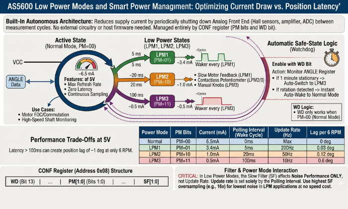
The AS5600 magnetic encoder includes a built-in power management architecture that reduces supply current by periodically shutting down the analog front end — the Hall sensor array, amplifier chain, and ADC — between measurement cycles. This mechanism is controlled entirely through the PM[1:0] bits in the CONF register and requires no external power switching circuitry, no sleep/wake command sequence from the host microcontroller, and no firmware state machine to manage the transition between active and low-power states. The device handles all power cycling autonomously once the PM bits are configured.
Understanding the power mode architecture is also important beyond simply reducing the current drawn. The polling interval for each of the low-power modes has a direct relationship with the maximum rate at which the angular information may be updated for the host system. If the application involves continuous rotation of a shaft, such as a motor, a conveyor, or a rotating antenna, a polling interval that is too long with respect to the rotation speed will cause the ANGLE register to be read with information that is no longer current, thereby causing a position reading that lags behind the actual physical angle by up to one full polling period. Therefore, the selection of the proper power mode requires consideration of both the power requirements and the maximum allowable position update latency for a particular application.
Power Mode Configuration via PM[1:0] Bits
The PM[1:0] bit field occupies bits 1:0 of the low byte of the CONF register (address 0x08). Four states are defined:
PM = 0b00 — Normal Mode
The analog front end operates continuously with no power cycling. The ADC samples at its maximum rate, the CORDIC processes each sample immediately, and the ANGLE register is updated at the full output data rate. Supply current in normal mode is approximately 6.5 mA from a 5V supply. This is the correct mode for all motor control applications, high-speed shaft monitoring, and any application where the position must be tracked continuously without latency.
PM = 0b01 — Low Power Mode 1 (LPM1)
The analog front end is powered down between measurement cycles. The device wakes autonomously every 5 ms, performs a single angle measurement, updates the ANGLE register, then returns to the low-power sleep state. Supply current drops to approximately 3.4 mA — a reduction of approximately 48% relative to normal mode. LPM1 is the appropriate choice for slow motor feedback applications where a 5 ms position update interval is acceptable, or for battery-powered designs where current reduction is necessary but sub-10 ms latency is still required.
PM = 0b10 — Low Power Mode 2 (LPM2)
Wake interval extends to 20 ms, with supply current dropping to approximately 1.0 mA. The ANGLE register is updated four times per second at this polling rate. LPM2 is suitable for slow position monitoring applications — panel knob position, damper or valve position feedback, joystick center detection — where angular position changes slowly and a 20 ms update latency is imperceptible to the end user or the control system.
PM = 0b11 — Low Power Mode 3 (LPM3)
The longest polling interval: 100 ms between measurement cycles, with supply current at approximately 0.5 mA. The ANGLE register updates ten times per second. LPM3 is appropriate only for very slow position indication — a rotary selector switch position, a manual adjustment knob that is set infrequently — where the shaft rotates slowly and update latency of up to 100 ms is acceptable. At 100 ms polling, a shaft rotating at just 6 RPM completes 1° of rotation between samples — meaning the position reading is perpetually 1° behind the true angle even at this modest speed. LPM3 is not suitable for any application involving continuous rotation above approximately 3–4 RPM.
Selecting the Correct Power Mode for Your Application
The selection between normal mode and the three low power modes is not purely a current consumption decision — it is a latency vs. power trade-off that must be evaluated against the rotational dynamics of the specific application. The following framework covers the most common application categories:
Motor commutation and FOC control — use Normal Mode
Field oriented control needs constant fast updates of motor position to keep the current vector correctly aligned. At speeds above 100 RPM, a polling interval of 5 ms (LPM1) creates a position error greater than 3 degrees each update cycle. This level of error would cause the current control loop to be unstable. Therefore normal mode will always be the appropriate mode for closed-loop motor control applications. Additionally, the 6.5mA current draw is a constant cost of the control architecture of the motor control and is not significant compared to the current of the motor phases.
Stepper motor position verification — use LPM1 or Normal Mode
Stepper motors typically operate at speeds between 60 and 600 RPM (1–10 revolutions per second). At 600 RPM, a 5 ms LPM1 polling interval introduces a maximum position lag of 18°. Acceptability depends on the application. In 3D printer extruders, 18° lag is fine since missed steps produce larger, detectable errors. Use Normal Mode for high precision CNC positioning.
Contactless potentiometer replacement — use LPM2 or LPM3
Humans operate panel knobs, HVAC dampers, and manual controls at speeds well below 60 RPM.. A 20 ms update interval (LPM2) produces a maximum position lag of 7.2° at 60 RPM — imperceptible to a human operator and entirely adequate for the control system response. At typical knob manipulation speeds of 10–20 RPM, LPM3’s 100 ms interval produces only 6° of lag — acceptable for most panel control applications and worth the 5× current reduction relative to LPM2.
Battery-powered IoT position sensing — use LPM3
In LPM3, remote sensor nodes that are transmitting shaft position data wirelessly can be powered by a 1000mAh Li-ion cell for approximately 80 days before being depleted. In LPM3, the AS5600’s (and its I2C pull-up resistors) continuous current draw of 0.5mA at a maximum transmit interval of 2 minutes will not have a noticeable effect on the overall system power budget.
Watchdog Function and Automatic Safe-State Behavior
Enable the watchdog with the WD bit in the CONF register. It monitors the ANGLE register continuously in normal mode. When the angle output does not change for more than one minute, the watchdog automatically puts the device into LPM3 mode from the normal mode. This reduces the supply current from 6.5 mA to 0.5 mA without the need for firmware.
As soon as the shaft starts rotating and the ANGLE Register starts changing again, the watchdog function automatically puts the device back into normal mode. This establishes an automatic idle power reduction function, especially useful for applications where the shaft is stationary for long periods but needs to react quickly to shaft rotation when it does occur.
The watchdog function only works when the device is running in normal mode (PM bits set to 0b00). The watchdog does not work if one of the three low-power modes is chosen by setting the PM bits. In this case, the device is already running in a low-power mode where it polls the registers for changes. In this case, the watchdog cannot automatically switch the device from normal mode to LPM3 mode, as this would be redundant.
Enable the watchdog function
Enable the watchdog function for applications where the device needs to run in normal mode for maximum responsiveness during periods of active shaft rotation, but also needs to automatically switch to low-power mode during periods of no rotation.
Disable the watchdog function
Disable the watchdog function (default: WD = 0) for applications where the device needs to run continuously in normal mode regardless of the state of the shaft rotation. In motor control, when fixed under load, continuously update the angle register at maximum speed to maintain torque control.
Interaction Between Power Mode and Filter Settings
There is a non-obvious interaction between power mode selection and slow filter (SF[1:0]) setting in the CONF register. In normal mode, the slow filter oversampling ratio directly sets the ANGLE register update rate – at 16x oversampling the update rate will be about 14.7 Hz regardless of how fast the host reads the register. In low power modes, however, the update rate is instead based on the polling interval and not the filter oversampling ratio because only one measurement is made during each wake cycle.
As a result, in LPM1, LPM2, or LPM3, the slow filter setting does not affect the update rate because the device will wake once for each polling interval, take a single measurement (with configured oversampling), update ANGLE register, then return to sleep. Although there’s oversampling on the single wake measurement which reduces noise on the reading, this cannot affect subsequent measurements with regard to exceeding the defined update rate based on the specified polling interval.
This means the SF bits should be configured for noise performance rather than update rate when operating in any low power mode. In LPM applications, 16x oversampling (SF = 0b00) provides the lowest noise per reading at no update rate cost — the polling interval already dominates the overall update latency, and the additional time spent oversampling within each wake cycle is small relative to the sleep period.
Interfacing the AS5600 with Arduino — Wiring and Code
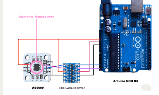
The AS5600 encoder connects to Arduino and ESP32 boards via the standardized I2C protocol. The wiring setup requires at least 4 wires (VDD, GND, SDA, SCL) with a need for two pull-up resistors on the I2C lines if they do not exist on the breakout module. The AS5600 may operate at the same voltage level as the Arduino without needing an additional level shift; however, if you connect a 3.3V AS5600 to a 5V I2C bus, you will need to check the compatibility of signal voltages according to the specifications provided in this section.
The material in this section will detail how to set up all of the necessary hardware connections between an Arduino Uno or Nano, provide instructions for implementing I²C at the raw register level to read angle readings without any external libraries, and show how to use the RobTillaart AS5600 Library to provide higher level functions, such as cumulative position tracking and angular speed computations.
Hardware Wiring — AS5600 to Arduino Uno and Nano
The Arduino Uno and Nano have two dedicated pins, SDA at A4 and SCL at A5, for exposing the I2C bus; these pins connect internally to the ATmega328P’s Two-Wire Interface (TWI) peripheral hardware. On Arduino Uno R3 and later, SDA and SCL near AREF can also be accessed via labeled pins, both connecting to the same TWI.
The complete wiring connection between the AS5600 and an Arduino Uno or Nano is:
Supply voltage selection
Supply voltage selection is the first decision in the wiring process. The Arduino Uno and Nano provide both 5V and 3.3V rails from their onboard regulators. Many inexpensive AS5600 breakout boards operate at both voltages; however, if there is a pull-up resistor on an AS5600 breakout board, it will likely be at 5V. Therefore, it is best to connect VDD from an AS5600 breakout module to the 5V pin of the Arduino for those boards. If the board is rated for 3.3 V only, connect it to the Arduino’s 3.3 V output to function correctly. Connecting 5V to a 3.3V rated AS5600 will melt the board.
I2C voltage compatibility
Pay attention to I2C voltage compatibility when the AS5600 runs at 3.3 V and the Arduino uses 5 V logic.. The ATmega328P I2C output is open-drain — it pulls the bus LOW actively and releases to HIGH through the pull-up resistors. If pull ups use 5V, SDA and SCL reach 5V, exceeding the AS5600’s 3.6V maximum for a 3.3V device. The safe solution is to reference the pull-up resistors to 3.3V rather than 5V, which limits the HIGH level to 3.3V — within the ATmega328P’s logic HIGH input threshold and within the AS5600’s absolute maximum rating. A dedicated I2C level shifter (such as the BSS138-based bidirectional level shifter) is the more robust solution for production designs.
Pull-up resistors
Pull-up resistors must be present on both SDA and SCL. If the AS5600 breakout module does not include onboard pull-ups, add 4.7 kΩ resistors between each I2C line and VDD. If the module includes onboard pull-ups and the Arduino also has pull-ups on its I2C pins (the Uno does not, but some shields do), the parallel combination of two 4.7 kΩ resistors produces an effective 2.35 kΩ pull-up — still within the valid range for 400 kHz fast mode operation.
Do not connect the PGO pin to GND in a standard I2C wiring setup. Leave it floating or connect it to VDD through a 10 kΩ resistor. As detailed in the pinout section, shorting PGO to GND activates 3-wire mode and disables the OUT pin — a mistake that has no visible effect on I2C angle reading but silently prevents analog and PWM output from functioning.
Reading Angle Data via I2C — Register Access Code
The following Arduino sketch reads the 12-bit angle value directly from the AS5600 ANGLE register using raw Wire library calls, without any external AS5600-specific library. Use this implementation to minimize dependencies, learn I2C register access, or port to non-Arduino platforms without the RobTillaart library.
#include <Wire.h>

#define AS5600_ADDRESS   0x36

#define REG_STATUS       0x0B

#define REG_ANGLE_HIGH   0x0E

#define REG_ANGLE_LOW    0x0F

// Read a single byte from the specified AS5600 register

uint8_t readRegister(uint8_t reg) {

  Wire.beginTransmission(AS5600_ADDRESS);

  Wire.write(reg);

  Wire.endTransmission(false);        // Repeated start — keep bus active

  Wire.requestFrom(AS5600_ADDRESS, 1);

  return Wire.read();

}

// Read the 12-bit angle from ANGLE register (0x0E–0x0F)

uint16_t readAngle() {

  uint8_t highByte = readRegister(REG_ANGLE_HIGH);

  uint8_t lowByte  = readRegister(REG_ANGLE_LOW);

  // High byte bits [3:0] are angle bits [11:8]

  // Low byte bits  [7:0] are angle bits [7:0]

  return ((uint16_t)(highByte & 0x0F) << 8) | lowByte;

}

// Check magnet detection status

bool magnetDetected() {

  uint8_t status = readRegister(REG_STATUS);

  return (status & 0x20);             // MD flag is bit 5

}

void setup() {

  Serial.begin(115200);

  Wire.begin();

  Wire.setClock(400000);              // Fast mode — 400 kHz

  Serial.println("AS5600 Magnetic Encoder — Angle Reader");

  // Always verify magnet presence before reading angle

  if (!magnetDetected()) {

    Serial.println("ERROR: Magnet not detected. Check alignment and STATUS register.");

    while (true);                     // Halt — do not proceed without valid magnet

  }

  Serial.println("Magnet detected. Reading angle...");

}

void loop() {

  uint16_t rawCount = readAngle();

  float angleDegrees = rawCount * (360.0 / 4096.0);

  Serial.print("Raw count: ");

  Serial.print(rawCount);

  Serial.print("  |  Angle: ");

  Serial.print(angleDegrees, 2);

  Serial.println("°");

  delay(50);                          // 20 Hz read rate — adjust for application

}
Key implementation points in this code:
The Wire.endTransmission(false) call on the register address write is a repeated start instead of a STOP on the I2C bus. This keeps the bus locked to the master from the address write to the subsequent read. This prevents any other master on the bus (if present) from inserting a transaction between the register pointer write and the byte read. On a one-master bus, repeated start is less critical, but it is the correct I2C sequence and should always be used.
The two-byte angle assembly ((highByte & 0x0F) << 8) | lowByte applies the 0x0F mask to the high byte before shifting. This mask discards unused high-byte bits [7:4] to prevent undefined behavior. Omitting it may cause incorrect readings on other registers.
The magnetDetected() check in setup() reads the STATUS register and tests bit 5 (the MD flag). Perform this check before using any angle reading as a valid position reference. Proceeding to read and use ANGLE register values without confirming MD = 1 risks using an invalid position reading — particularly problematic in motor control or position homing sequences where an invalid initial angle reference corrupts all subsequent position calculations.
Using the AS5600 Arduino Library (RobTillaart / AS5600.h)
However, the RobTillaart AS5600 library is the most popular and commonly used open-source library for the Arduino environment. This library abstracts the device’s I2C registers and has been thoroughly tested for functionality. This library includes functions for reading angles, magnetic status, the CONF register, multi-turn cumulative position, and angular velocity. In application-level development, where the focus is on the integration of the device rather than the raw interface to the registers, the use of the library can save considerable time and does not require the manipulation of the registers as explained in the previous section.
Open the Arduino IDE Library Manager, search AS5600, and install the library by Rob Tillaart. The library is compatible with Arduino Uno, Nano, Mega, ESP32, ESP8266, and any other platform supported by the Arduino Wire library.
Core functions for angle reading:
#include "AS5600.h"

AS5600 encoder;

void setup() {

  Serial.begin(115200);

  Wire.begin();

  encoder.begin(4);                   // Pass the DIR pin number if used

                                      // Use encoder.begin() if DIR not connected

  // Verify magnet presence before use

  if (!encoder.isConnected()) {

    Serial.println("AS5600 not found on I2C bus — check wiring.");

    while (true);

  }

  if (!encoder.detectMagnet()) {

    Serial.println("Magnet not detected — check alignment.");

    while (true);

  }

}

void loop() {

  // Read filtered angle in degrees (0.0 – 360.0)

  float angle = encoder.getAngle();

  // Read raw 12-bit count (0 – 4095)

  uint16_t rawCount = encoder.getRawAngle();

  // Read cumulative position in counts (tracks multiple revolutions)

  int32_t cumulative = encoder.getCumulativePosition();

  // Read angular speed in degrees per second

  float speed = encoder.getAngularSpeed();

  // Read AGC value for alignment diagnostics

  uint8_t agc = encoder.readAGC();

  Serial.print("Angle: ");     Serial.print(angle, 2);

  Serial.print("°  Raw: ");    Serial.print(rawCount);

  Serial.print("  Cumul: ");   Serial.print(cumulative);

  Serial.print("  Speed: ");   Serial.print(speed, 1);

  Serial.print("°/s  AGC: ");  Serial.println(agc);

  delay(10);                          // 100 Hz read rate

}
Critical usage notes for the library functions:
encoder.getCumulativePosition() tracks the total accumulated angle across multiple revolutions by detecting and counting 0/4095 wraparound events in the ANGLE register. Call this function at least four times per revolution to detect wraparound events correctly. Increase the call rate with speed. At 300 RPM, call it at least twenty times per second. Missing this rate causes permanent position errors.
encoder.getAngularSpeed() computes speed from the time derivative of the angle reading between successive calls. The accuracy of the speed calculation depends on the time interval between calls — very short intervals (under 5 ms) produce noisy speed estimates due to the quantization of the 12-bit angle output, while very long intervals (over 100 ms) produce estimates that lag true speed during acceleration. For motor speed feedback, call intervals between 10 ms and 50 ms provide a practical balance between noise and responsiveness.
encoder.begin(dirPin) accepts an optional Arduino pin number for the DIR pin. The library toggles DIR to control rotation polarity when mounting is unknown; if DIR is hardwired, call encoder.begin() without arguments.
AS5600 Register Configuration — CONF Register Deep Dive
The CONF register is the primary configuration interface for the AS5600 magnetic encoder. The primary behavioral characteristics of the device, including power mode, output type, noise filtering, PWM frequency, hysteresis, and watchdog functions, are all controlled by a single 14-bit register: CONF. This spans two consecutive I2C addresses: 0x07 (high byte, bits 13:8), and 0x08 (low byte, bits 7:0). Bits 15 and 14 are unused in the 16 bit register space and always read as zero.
Understanding the CONF register at the bit-field level is essential for any application that moves beyond the default factory configuration. The default power-on state of all CONF bits is zero — meaning normal power mode, analog full-range output, no hysteresis, maximum slow filter oversampling, no fast filter threshold, lowest PWM frequency, and watchdog disabled. For many applications this default state is not optimal, and writing the correct CONF value before beginning operation significantly improves measurement quality, power efficiency, and output behavior.
PM[1:0] — Power Mode Bits (Bits 1:0, Low Byte)
The PM bits select the operating power mode as covered in full detail in the Low Power Modes section. Write PM bits as part of a complete CONF register write, not as an isolated single bit modification. The AS5600 does not support read-modify-write at the bit level through I2C. To change only the PM bits without disturbing other CONF settings, the firmware must read the current CONF value, modify only the PM bits in the local variable, and write the full modified value back to both CONF register addresses.
HYST[1:0] — Hysteresis Bits (Bits 3:2, Low Byte)
The HYST bits apply a digital hysteresis band around the ANGLE register output to suppress output bit toggling when the shaft is stationary or moving very slowly at a position near an LSB transition boundary. Four hysteresis levels are available:
Without hysteresis, a shaft at a static position near an LSB transition boundary will cause the output to oscillate between two values as thermal noise and magnetic field micro-variation cause the CORDIC output to change between the two values on either side of the transition. This causes a jittery ANGLE value, generates spurious interrupts, produces incorrect velocity, and creates audible noise in audio control applications.
Setting one or two LSBs of hysteresis effectively stops this toggling for a static or near-static shaft position while introducing a small “dead band” around each count transition. In the majority of cases, the recommended default is to set the HYST bits to 0b01 (1 LSB), which will stop the output jitter without introducing a noticeable “dead band” in the shaft position information.
Set hysteresis to 0b11 in extremely noisy magnetic environments when 1 to 2 LSB hysteresis fails to stop toggling.
OUTS[1:0] — Output Stage Bits (Bits 5:4, Low Byte)
The OUTS bits select the electrical output mode of the OUT pin, as described in full in the Output Modes section. The register-level encoding is:
Set OUTS to 0b00 when using I2C output and not the OUT pin, and configure a known state to avoid unintended loading.
PWMF[1:0] — PWM Frequency Bits (Bits 7:6, Low Byte)
The PWMF bits select the PWM carrier frequency when OUTS = 0b10 (PWM mode). Four frequencies are available:
Higher PWM frequencies reduce the time required for hardware input capture to compute the duty cycle. At a PWM frequency of 115 Hz, it takes up to 8.7 ms to make a single period measurement. This restricts the maximum effective angle update rate to about 115 Hz. At a PWM frequency of 920 Hz, it only takes 1.1 ms to measure each period, enabling angle updates up to 920 Hz. This is adequate for most low to medium-speed motor feedback applications that employ PWM output. The downside to utilizing higher PWM frequencies is that they also require a faster input capture timer in the host microcontroller and will produce more switching noise at the OUT pin and in the associated wiring.
For most PWM output applications, PWMF = 0b10 (460 Hz) provides a practical balance between update rate (up to 460 angle readings per second), timer resolution requirements, and switching noise. Use PWMF = 0b11 (920 Hz) only when the application genuinely requires sub-2 ms angle update latency through the PWM output path.
SF[1:0] — Slow Filter Bits (Bits 9:8, High Byte)
The SF bits select the digital filter’s oversampling ratio before updating the ANGLE register from the CORDIC output. Four ratios are available:
As you increase your oversampling ratio, you’ll reduce your output noise by averaging out many more ADC samples when making an update to the ANGLE register; conversely, a lower oversampling ratio will allow for more frequent updates at the expense of increased output noise. The default power-on configuration sets SF to 0b00, applying 16x oversampling to minimize output noise at the cost of a low update rate. Slow positioning applications tolerate this default well. Motor control applications require SF reconfiguration before deployment.
For motor commutation and FOC control, use SF = 0b11 (2x oversampling, ~116 Hz update rate) combined with the fast filter threshold to handle rapid angular changes. SF = 0b00 (16x oversampling) provides the smoothest output with the lowest noise floor for contactless potentiometer replacement and panel controls. For the stepper motor position verification, SF = 0b01 or 0b10 offers a practical middle ground between noise and update rate.
FTH[2:0] — Fast Filter Threshold Bits (Bits 12:10, High Byte)
The FTH bits configure the fast filter threshold — the angular step size above which the digital filter switches from slow (oversampled) mode to fast (single-sample) mode for that individual update cycle. This mechanism allows the ANGLE register to track rapid angular changes with low latency while maintaining low-noise output during slow or stationary operation.
When the angular change between two consecutive measurement cycles exceeds a threshold set during programming of the microcontroller unit, the slow filter is bypassed for this single cycle, and the raw output of the CORDIC algorithm is written to the ANGLE register. This process ensures a rapid response to swift angular changes while minimizing noise during steady-state operation.
In cases where motor control is required with I2C output and where the slow filter is enabled, setting FTH to 0b001 (6 LSBs, 0.53°) ensures a fast filter response to angular changes greater than 0.53°. This ensures commutation-relevant position changes while maintaining a filtered output during near-stationary holding torque conditions. The fast filter should be disabled (FTH set to 0b000) for position sensing applications where noise performance is critical and where rapid transient response is not required.
WD — Watchdog Bit (Bit 13, High Byte)
The WD bit enables the watchdog function as described in the Low Power Modes section. In the CONF register, the following applies: If WD is set to 0, the watchdog is disabled (default); if WD is set to 1, the microcontroller will automatically go into LPM3 after an approximate static angle output of 1 minute. Set WD to 1 for applications that need responsiveness in typical mode and automatic reduction of idle power. Leave WD set to 0 for all motor control applications, as well as for any application that needs continuous updates to the ANGLE register, regardless of shaft motion state.
Recommended CONF Register Values by Application
These values are starting-point recommendations — validate each setting against the specific noise, speed, and power requirements of the target application before committing to OTP burn.
AS5600 Magnetic Encoder Applications
The AS5600 magnetic encoder occupies a well defined position in the sensor landscape. It delivers 12-bit absolute angle measurement at low cost, requires minimal host processing overhead, and survives the mechanical and environmental conditions that destroy contact-based sensors. The four application categories below cover the primary deployment contexts for the AS5600 in current hardware designs and identify the performance boundaries where an alternative sensor becomes necessary.
Brushless Motor FOC Position Feedback
In Field Oriented Control (FOC) of brushless DC motors, the continuous knowledge of the rotor’s electrical position is a essential for accurate alignment of the current vector and optimal torque production. The AS5600 Magnetic Encoder provides precise rotor position feedback by using a diametrically magnetized magnet mounted on the motor shift. The AS5600 mounted on a small PCB with a direct view of the shaft, with the standard air gap of 0.5–3 mm as defined in the mechanical housing.
The angle update rate requirement for FOC is determined by the motor’s maximum electrical frequency.
Formula:
For a motor with pole pair count P spinning at N RPM, the electrical frequency is:
Consider a 7 pole pair motor commonly used in hobby brushless motors. The motor spins at 3000 RPM; this yields a rotor electrical frequency of 350 Hz, which means the motor will complete one full electrical cycle every 2.86 milliseconds. The current control loop must update at least 2 times the electrical frequency (per Nyquist) to accurately track the rotor position without aliasing effects. The target of most FOC implementations is to have update rates that are 4-10× the electrical frequency, therefore the AS5600 must provide position readings at 1400-3500 Hz for a 7 pole-pair hobby brushless motor, well beyond the maximum update rate (~116 Hz) of the AS5600 in normal mode with 2× oversampling.
This primary limitation of using AS5600 in high-speed field-oriented control (FOC) applications is its update rate constraint. The SimpleFOC library , a widely used open-source solution for FOC implementation on platforms such as Arduino Uno and ESP32, supports positionsensing via the AS5600. In practice, it performs reliably up to approximately 600–800 RPM on the Arduino Uno, primarily due to I²C read limitations within the main application loop. On the ESP32, higher performance is achievable—typically up to 3000–4000 RPM—thanks to faster I²C support and the ability to offload position reading to a second CPU core.
For applications requiring higher sampling rates, the AS5048A operating in SPI mode is a suitable upgrade, offering read rates of up to 10 kHz.
The single fixed I2C address (0x36) limits each I2C bus to one AS5600 — meaning a multi-motor FOC system requires either multiple I2C buses, an I2C multiplexer (adds latency), or transitioning to the AS5048B which supports configurable I2C addresses.
Contactless Potentiometer Replacement
ams OSRAM designed the AS5600 specifically to replace mechanical potentiometers and the IC excels in this role. With a conventional rotary potentiometer, you have degradation due to wear of the resistive element (which creates an increase in resistance), wiper contamination and oxidation of contact – all of which usually leads to a conventional rotary potentiometer failing after between 10 & 100K rotations (depending on quality grade). The AS5600 has no such degradation mechanism, nor any theoretical limit on the number of rotation cycles possible. Shaft bearings represent the only mechanical wear component in an AS5600 based assembly. Engineers select them independently of the sensor based solely on the application’s load and rotation cycle requirements.
The analog output mode maps directly to the electrical function of a potentiometer wiper voltage:. Connect VDD to the potentiometer high terminal equivalent, GND to the low terminal equivalent, and OUT to the wiper terminal equivalent. The receiving circuit, whether an ADC input, op-amp, or legacy analog control circuit, sees a voltage that varies linearly with shaft angle across the programmed rotation range.
If a device has a limited rotation range. Examples of such devices would include a 270° audio-level knob and a 300° HVAC damper actuator. In these cases, the system will program ZPOS and MPOS to the endpoints of the mechanical range and then will remap the output of the DAC across the programmed mechanical travel range to create a total output of 10% to 90% of VDD. This allows for maximizing the effective resolution available from the DAC since there is no need for the receiving ADC to relate a subrange of the input voltage to a full control range in the firmware.
Advantages
The advantages of using this approach instead of using mechanical potentiometers for these applications include: no contact noise; no effects from vibrations on the output; protection from moisture infiltration through sealed or submerged enclosures (there are no electrical connections that could corrode); and the ability of the output to remain consistent across all temperatures from −40 degrees celsius to +125 degrees celsius without any resistance drift caused by the elements within an all-carbon or cermet potentiometer.
Stepper Motor Position Verification and Closed-Loop Control
Open-loop stepper motor control in 3D printing, CNC routing, and laboratory automation assumes the motor executes every commanded step without skipping. When mechanical binding, aggressive acceleration ramps, or resonance pushes the load beyond the motor’s holding torque, the motor silently misses steps and its actual position diverges from the commanded position. The AS5600 magnetic encoder detects this divergence at low cost by comparing the reported shaft angle against the expected position after each commanded move.
As the angular resolution of the AS5600 is 0.087°/LSB, it has a higher resolution and finer precision than the full step of a standard 1.8° stepper motor and can also detect individual missed full steps and groups of missed microsteps when operated at 32 microsteps per full step (1.8° ÷ 32 = 0.056°/microstep). Therefore, the AS5600 (when used with other components) can help to provide closed-loop corrections to the stepper motor either at the full step or microstepping resolutions.
The method for confirming the stepper’s position is simple: attach a diametric magnet to the stepper motor shaft, read the AS5600 ANGLE register after every instructed move, and then compare the two values by taking the difference between the two angles. If the difference exceeds a predetermined tolerance (generally considered as 2 to 5 complete steps (3.6°-9°) will result in an adjustment move or an indicated fault condition) that will then result in you performing a correction to correct the angle. This model can be found in the TMC2209 Closed Loop Reference Design from Trinamic and also in aftermarket 3D Printer upgrades.
Robotics Joint Angle Sensing and Gimbal Stabilization
The AS5600 angular sensor (used in many different types of robot arm applications) is becoming the choice for most of these types of applications. The typical method of mechanical integration for the AS5600 is through the use of a radius-matched NdFeB magnet that is press-fit into a 6mm diameter recess within the rotating joint hub. This configuration mounts the AS5600 on the stationary PCB at the fixed end of the joint, giving it direct magnetic access to the NdFeB magnet through the joint rotation gap. This configuration also eliminates the need for slip rings making it unnecessary for flexible wire routing through the joint and providing a clean optical path unobstructed by either dust or ambient lighting.
6-degree-of-freedom (DOF)
For a 6-degree-of-freedom (DOF) robot arm where each joint includes one AS5600, each AS5600 could be connected to either (1) six different I2C buses or (2) one TCA9548A, an 8-channel multiplexer. The TCA9548A adds approximately 1–2 milliseconds of switching time delay to each AS5600 reading when polling them sequentially — which is an acceptable delay for control loops operating between 50 Hz and 200 Hz but would likely pose timing challenges in very rapid manipulation activities.
In stabilization systems for cameras, such as 2 and 3-axis gimbals, the AS5600 absolute angle sensing technology provides the stabilization controller with an indication of tilt (pitch) and pan yaw) angles of the gimbal. In most cases, the use of absolute angle feedback from the AS5600 is preferred to incremental encoder feedback because it does not require a homing routine after the power is turned on and allows the gimbal to immediately establish its position in space upon power application. Additionally, the 12bit resolution of the AS5600 typically provides sufficient angular resolution (approximately 0.09° resolution per axis) for stabilizing a camera under normal cinematic frame rates. Alternatively, for use in professional broadcast gimbal applications where it is necessary to have sub0.01° angular resolution capability along with the ability to support multiple units over a bus, an upgrade to the AS5048B (14bit resolution with configurable I2C address) would be well suited.
AS5600 vs AS5048 vs AS5600L — Comparative Specification Analysis
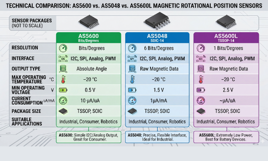
Selecting the most suitable angle sensor for your project, it is important to get a good understanding of the AS5600’s features (such as maximum angle of rotation, mechanical mounting options, electrical connections) and its architectural limitations (such as the I2C address being fixed, 12-bit resolution, and single axis output). The AS5600L and AS5048 are designed differently than each other, so this section will give you a specification comparison of these two products to help you make your decision.
AS5600 vs AS5600L
This document explains how the AS5600L is a different version of the AS5600 with one architectural improvement over the base AS5600: Its I2C address can be programmed, allowing for multiple AS5600L parts to live on a single I2C bus and eliminating the need for additional I2C multiplexers. The AS5600L solves the issue of wiring multiple sensors and preventing interference with a TCA9548A when using the AS5600.
One important trade-off made by the AS5600L in order to provide support for multiple addresses is that it does not provide an analog mode of operation at all. As such, the only output supported by the AS5600L at the OUT pin is a PWM output; there is no analog voltage output available. Therefore, if your application requires the use of an analog voltage output as a drop-in replacement for direct use of a potentiometer (for example, feeding into an existing analog system) for either legacy analog circuitry or an ADC without a PWM decode capability, you should not use the AS5600L as a drop-in replacement for the AS5600. Other than these differences, the AS5600L is identical to the AS5600 in terms of resolution (12 bits), CORDIC architecture, AGC loop, magnet specifications, SOIC-8 packaging, operating temperature range, and I2C register map.
Designs requiring analog output or a single sensor per bus choose the AS5600. Use the AS5600L when multiple magnetic encoders must share a single I2C bus and PWM or I2C digital output is acceptable.
AS5600 vs AS5048A and AS5048B
The AS5048 family (AS5048A and AS5048B) represents a step up in performance, interface flexibility, and operating envelope — at a correspondingly higher unit cost.
Resolution:
The AS5048 provides 14-bit angle output — 16,384 positions per revolution, compared to the AS5600’s 4,096. The angular resolution improves from 0.087°/LSB to 0.0219°/LSB — a 4× improvement. This 4× resolution improvement matters directly in precision applications. High accuracy gimbal stabilization, telescope mount tracking, precision valve control, and industrial servo systems all demand sub-0.1° accuracy across the full operating temperature range — a specification the AS5600 cannot meet but the AS5048 delivers reliably.
Interface:
The AS5048A uses SPI as its primary interface, achieving read rates above 10 kHz — more than 80× faster than the AS5600’s 400 kHz I2C fast mode in terms of achievable angle read throughput. This makes the AS5048A the correct choice for high-speed motor FOC applications where the AS5600’s I2C rate limits commutation performance. The AS5048B uses I2C with a configurable address (set by two address pins), supporting up to four AS5048B devices on a single I2C bus — directly addressing the multi-sensor limitation of the AS5600 without requiring a multiplexer.
Operating temperature:
Both AS5048 variants are specified to −40°C to +150°C — 25°C higher than the AS5600’s +125°C upper limit. For automotive underhood applications and industrial equipment near heat sources, this extended range matters.
Cost:
The AS5048 family commands a price premium of approximately 2–4× over the AS5600 in typical quantities. For high-volume consumer products or budget-constrained maker projects, the AS5600’s cost advantage is significant when its performance specifications are sufficient.
Common Troubleshooting Issues with the AS5600
The majority of AS5600 magnetic encoder integration failures fall into three categories: magnet-related hardware errors diagnosed through the STATUS register flags, I2C communication failures caused by wiring or address conflicts, and OUT pin failures caused by PGO pin misconfiguration on breakout modules. Each category has a distinct symptom pattern and a clear resolution path.
Magnet Not Detected — MD, ML, MH Status Flags
The STATUS register (address 0x0B) is the primary diagnostic instrument for all magnet-related failures. Before reading any value from the ANGLE register, read the STATUS register first and evaluate all three diagnostic flags.
MD = 0 (Magnet Not Detected)
The AGC has not detected a magnetic field within its operating range. The ANGLE register output is invalid and must not be used. Causes and resolutions:
- No magnet installed — verify the magnet is physically present above the IC
- Wrong magnet type — confirm diametric magnetization (not axial)
- Magnet too far — reduce the vertical air gap below 3 mm
- Magnet not centered — verify lateral alignment within ±0.25 mm of IC center
- Supply voltage unstable — measure VDD with a multimeter under load
MH = 1 (Magnet Too Strong)
The AGC is at its maximum gain limit because the magnetic field is too powerful for the AGC to compensate as the angle output is probably still in the right ballpark. High field strength degrades angle accuracy. Increase the vertical air gap between the magnet and IC surface to bring the AGC back within its valid operating range. If the assembly already uses more than 1 mm of air gap with a standard 6 mm diameter NdFeB magnet, switch to a smaller 4 mm diameter magnet or downgrade to a lower remanence grade such as N35 instead of N52.
ML = 1 (Magnet Too Weak)
Currently, the automatic gain control (AGC) has reached its maximum positive gain range but remains under 8mT (minimum magnetic force). The ANGLE register output will be disabled. If you’d like to resolve this issue, you could decrease the distance between the agent and the source of the magnet.If the air gap sits at its minimum practical value, upgrade to a larger diameter magnet or a higher grade NdFeB material such as N42 or N52. Alternatively, if the neutron could check his diametrically oriented magnetization, he may inadvertently set his measuring device to MD=1 and still be producing rather significant ML=1 through improper magnetic field alignment despite being very close in proximity.
The following diagnostic code reads all three STATUS flags and the AGC value simultaneously:
void printMagnetStatus(AS5600 &encoder) {

  uint8_t status = encoder.readStatus();

  uint8_t agc    = encoder.readAGC();

  Serial.print("MD: "); Serial.print((status >> 5) & 1);

  Serial.print("  MH: "); Serial.print((status >> 3) & 1);

  Serial.print("  ML: "); Serial.print((status >> 4) & 1);

  Serial.print("  AGC: "); Serial.println(agc);

}
Run this diagnostic at startup and log the AGC value during final mechanical assembly to confirm the air gap is within the optimal range (AGC between 80 and 175 for most standard magnet configurations).
I2C Communication Failure — Address Conflicts and Pull-Up Issues
I2C communication failure with the AS5600 manifests as Wire.endTransmission() returning a non-zero error code, Wire.requestFrom() returning 0 bytes, or the RobTillaart library’s encoder.isConnected() returning false. The diagnostic approach follows a systematic hardware-first sequence:
Step 1 — Run an I2C bus scanner
Upload a standard I2C scanner sketch (widely available in Arduino examples) that iterates through all 127 I2C addresses and reports which ones acknowledge. A healthy AS5600 on a correctly wired bus will appear at address 0x36. If 0x36 does not appear in the scan results, the problem is hardware — not firmware.
Step 2 — Verify pull-up resistors
Measure the voltage on SDA and SCL with no I2C transaction in progress. Both lines should read VDD (approximately 3.3V or 5V depending on the system) when the bus is idle. A reading of 0V indicates missing pull-ups or a short to GND. A reading below VDD but above 0V indicates pull-up resistors are present but too high in value, or a device on the bus is holding the line low.
Step 3 — Check for address conflicts
If the I2C scanner shows devices at unexpected addresses, another device on the bus may share address 0x36. Common devices with addresses near 0x36 include some OLED display controllers (0x3C, 0x3D) and certain RTC modules. These do not conflict with 0x36 directly but confirm the scanner is working correctly. If another device occupies address 0x36 on the bus, remove it from the shared bus or move it to a dedicated I2C bus.
Step 4 — Verify VDD and GND continuity
A floating or intermittent VDD connection produces I2C failures that are indistinguishable from pull-up or address issues at the software level. Measure VDD directly at the AS5600 package pin (or breakout module VDD pad) with the system powered. Confirm it reads within the specified supply voltage range.
Step 5 — Check for 3.3V/5V level mismatch
Powering the AS5600 from 3.3V while connecting it to a 5V Arduino I2C bus with 5V pull-ups drives the SDA and SCL lines to 5V, exceeding the AS5600 maximum signal pin voltage of VDD + 0.3V.. This can cause the device to appear to acknowledge intermittently or not at all, depending on the exact voltage and device tolerance. Resolve by referencing the pull-up resistors to 3.3V.
OUT Pin Not Functioning — PGO Resistor Issue on Breakout Modules
When the OUT pin produces no analog voltage variation and no PWM pulses despite correct I2C angle reading, the PGO-to-GND resistor on the breakout module is almost always the cause. AS5600 user communities worldwide report this as the most frequent hardware failure. The PGO pin section below explains the root cause and full resolution.
Diagnosis: Confirm I2C is working and ANGLE register values change correctly with shaft rotation. Set CONF register OUTS bits to analog mode (0b00) and measure the OUT pin with a voltmeter while rotating the shaft. If the voltage does not vary between approximately 10% and 90% of VDD across the rotation range, the OUT pin is not functioning as an analog output.
Identification: Visually inspect the AS5600 breakout module PCB under magnification. Look for a small resistor — typically a 0402 or 0603 package — connected between the PGO pin pad and the GND plane. On some modules this is a labeled solder jumper. On others it is an unmarked 0Ω resistor.
Resolution: Remove the resistor connecting PGO to GND using a soldering iron with a fine tip and flux. After removal, the OUT pin should immediately begin functioning as an analog or PWM output according to the CONF register OUTS setting. The hardware fix alone restores full OUT pin functionality, the firmware requires no changes.
If removing the resistor is not feasible (surface mount package too small, risk of PCB damage). An alternative workaround is to cut the PCB trace between PGO and GND with a sharp blade. Then verify continuity is broken with a multimeter before powering up.
AS5600 Module Breakout Boards — What to Look for When Purchasing
The AS5600 magnetic encoder is available on breakout modules from several suppliers ranging from established electronics distributors to low-cost generic manufacturers. The quality, feature set, and hardware correctness of these modules vary significantly — and the wrong module choice introduces hardware problems that consume debugging time disproportionate to the cost difference between modules.
Various suppliers have breakout modules based on the AS5600 magnetic encoder, from established electronics distributors to low-cost generic suppliers. The quality, features, and accuracy of each type of module will be different. Selecting the wrong type of breakout module can create hardware issues and will lead to a proportionately greater time spent on debugging than the price difference between types of breakout modules.
Seeed Studio Grove AS5600
The Seeed Grove module uses a Grove I2C connector (4-pin JST, 2 mm pitch) with onboard 3.3V/5V compatibility through a voltage regulator and level shifter. The module includes onboard pull-up resistors. The Grove mechanical format simplifies connection to Grove-compatible development boards but limits direct use with standard 2.54 mm header systems without a Grove-to-header adapter. This module leaves PGO disconnected from GND — the OUT pin delivers correct analog and PWM output without hardware modification.
The module includes a magnet holder designed for a 6 mm diametric NdFeB magnet aligned with the IC.
Adafruit AS5600
The Adafruit breakout board features STEMMA QT (Qwiic-compatible) connectors allowing a tool-free I2C connection to the STEMMA QT/Qwiic ecosystems. There are also traditional 2.54mm through-hole headers for use with breadboards. The breakout board includes onboard pull-up resistors referenced to the 3.3V rail, therefore, providing 3.3V output from the included 3.3V Regulator (input voltage range of 3.3-5V). Adafruit publishes complete documentation on the Adafruit Learning System. The breakout exposes the PGO pin on the header and leaves it disconnected from GND at the factory.
Generic AS5600 Modules
In the maker community, generally inexpensive generic modules (typically under $2 USD) are common and work well for I2C digital output applications. Modules present one critical hardware risk: many ship with a PGO-to-GND resistor installed that permanently disables the OUT pin analog and PWM output. If you purchase them in large quantities, always request a PCB schematic diagram from the manufacturer or buy a single unit for inspection before making an order for a greater quantity. Generic modules often omit onboard pull-up resistors — verify their presence before powering up and add 4.7 kΩ external resistors on SDA and SCL if the module lacks them.
Key purchasing checklist:
Before committing to any AS5600 breakout module, verify the following:
- PGO pin routing confirmed — not shorted to GND (or solder-jumperable)
- Onboard pull-up resistors present and correctly valued for target voltage (2.2 kΩ for 3.3V, 4.7 kΩ for 5V)
- VDD voltage range compatible with target system (3.3V-only, 5V-only, or auto-switching)
- OUT pin accessible on header or solder pad
- Magnet holder or alignment feature present if mechanical integration is required
- Datasheet or schematic available from supplier for verification
Frequently Asked Questions About the AS5600
The AS5600 provides 12-bit resolution, giving 4096 positions over 360°. This corresponds to approximately 0.088° per step. Its typical accuracy is around ±0.5°, which is higher than the resolution.
No. The AS5600 uses a fixed I²C address (0x36), so multiple devices on the same bus will cause conflicts. Use an TCA9548A or choose the AS5600L, which supports programmable addresses.
It requires a diametrically magnetized (two-pole) magnet. ams OSRAM recommends NdFeB magnets Grade N35 or higher, centered within ±0.25 mm of the IC and maintained at an air gap of 0.5–3 mm above the chip surface.
The AS5600L supports configurable I²C addresses, allowing multiple sensors on one bus. However, it does not provide analog output, unlike the standard AS5600.
The AS5600 requires no calibration for basic operation. The internal AGC automatically compensates for magnet gap variation, temperature drift, and magnet aging. For constrained angular ranges, the firmware writes ZPOS and MPOS via I²C to define the zero reference and output endpoint.
Conclusion — When to Use the AS5600 and Design Recommendations
By putting together many different features, the AS5600 magnetic encoder has several advantages including: 12-bit absolute angle resolution; contactless Hall effect sensing (meaning there is no direct contact between the encoder and whatever object it is sensing); three output modes (analog, PWM and I2C); a wide operational temperature range of -40 to +125 degrees celsius; and low cost per unit in comparison to other encoders – all packaged together in a small SOIC-8 package that works with microcontroller’s operating at 3.3 volts or 5 volts, requires only four wires and two pull-up resistors! If your application falls within these limits, the AS5600 magnetic encoder provides a very reliable, low-cost, and easy-to-use position sensing solution for any level of hardware design/development.
However, the AS5600 has three architectural constraints that define the boundaries of appropriate use: a fixed I2C address that limits each bus to one device, a 12-bit resolution ceiling that is insufficient for sub-0.1° accuracy applications, and a maximum angle update rate of approximately 116 Hz in normal mode with minimum oversampling — a limit that constrains high-speed motor commutation performance.
The decision framework for sensor selection is straightforward:
AS5600:
- The I2C bus needs to have one axis of rotation with absolute angles utilizing
- The 12 bit resolution (±0.5° typical accuracy) and this is the basis for the application.
- Using an output of either analogue, PWM or I2C digital will suffice.
- Operating temperature cannot exceed +125°C
- The cost and simplicity of design have high priority.
AS5600L:
- Multiple magnetic encoders must share a single I2C bus
- The application uses only PWM or I2C digital output — no analog output.
- 12-bit resolution is sufficient
AS5048B:
- Required resolution for 14-bit is (0.022°/LSB, ±0.05° typical accuracy)
- The design requires multiple encoders per I2C bus with configurable addressing.
- The application operates at temperatures above +125°C and up to +150°C.
AS5048A:
- Maximum angle read rate is required (SPI interface, >10 kHz read throughput)
- High-speed FOC motor control above 3000 RPM is the target application
- 14-bit resolution is required with minimum I2C bus complexity
The AS5600 magnetic encoder continues to be appropriate for the majority of makers, prototypers and light industrial applications such as eliminating the use of contactless potentiometers, checking the position of stepper motors, monitoring the position values at the common joints of a robot, and providing feedback from motors operating at slow to medium speeds or controlling panels. The limitations of this device only begin to apply as indicated by the above performance envelopes, at which point the available options for an upgrade path within the ams OSRAM family will be well documented, and any experience with the device’s registers will transfer directly to the AS5048 devices will provide helpful information.

COMMENTS