Introduction
Modern industrial and IoT systems rely heavily on efficient and reliable power management. Whether it is an industrial automation controller, a remote IoT sensor node, or an embedded communication module, electronic devices often require stable low-voltage power rails derived from higher-voltage sources. This is where DC-DC converters play a critical role in electronic system design.
In many industrial environments, a common power source is a 12V or 24V supply rail, while the internal electronics—such as microcontrollers, sensors, and wireless modules—typically operate at 5V, 3.3V, or even lower voltages. Converting these voltages efficiently while maintaining reliability, thermal stability, and low electromagnetic interference (EMI) is essential for long-term system performance. Among various power conversion solutions, the DC-DC buck converter is one of the most widely used architectures for stepping down voltage in modern embedded systems.
Why DC-DC Converters in Your Embedded Design?
A buck converter IC integrates the control circuitry required to efficiently reduce the voltage from a higher input level to a regulated lower output. Compared with linear regulators, buck converters offer significantly higher efficiency, especially when the input voltage is much higher than the required output voltage. This makes them ideal for industrial electronics, IoT devices, battery-powered systems, and embedded platforms where power efficiency and heat dissipation are critical considerations.
However, selecting the right converter is not always straightforward. Engineers must evaluate multiple buck converter IC features, including input voltage range, output current capability, switching frequency, efficiency, protection mechanisms, and thermal performance. This article will cover the comprehensive guide on how to select the right DC-DC converter for your design application.
What Is a DC-DC Buck Converter?
A DC-DC buck converter is a type of switching power supply designed to efficiently step down a higher DC voltage to a lower DC voltage. It is one of the most widely used power conversion solutions in modern electronics, particularly in industrial systems, embedded devices, and IoT applications where efficient power management is essential.
Buck converter consists of several key components:
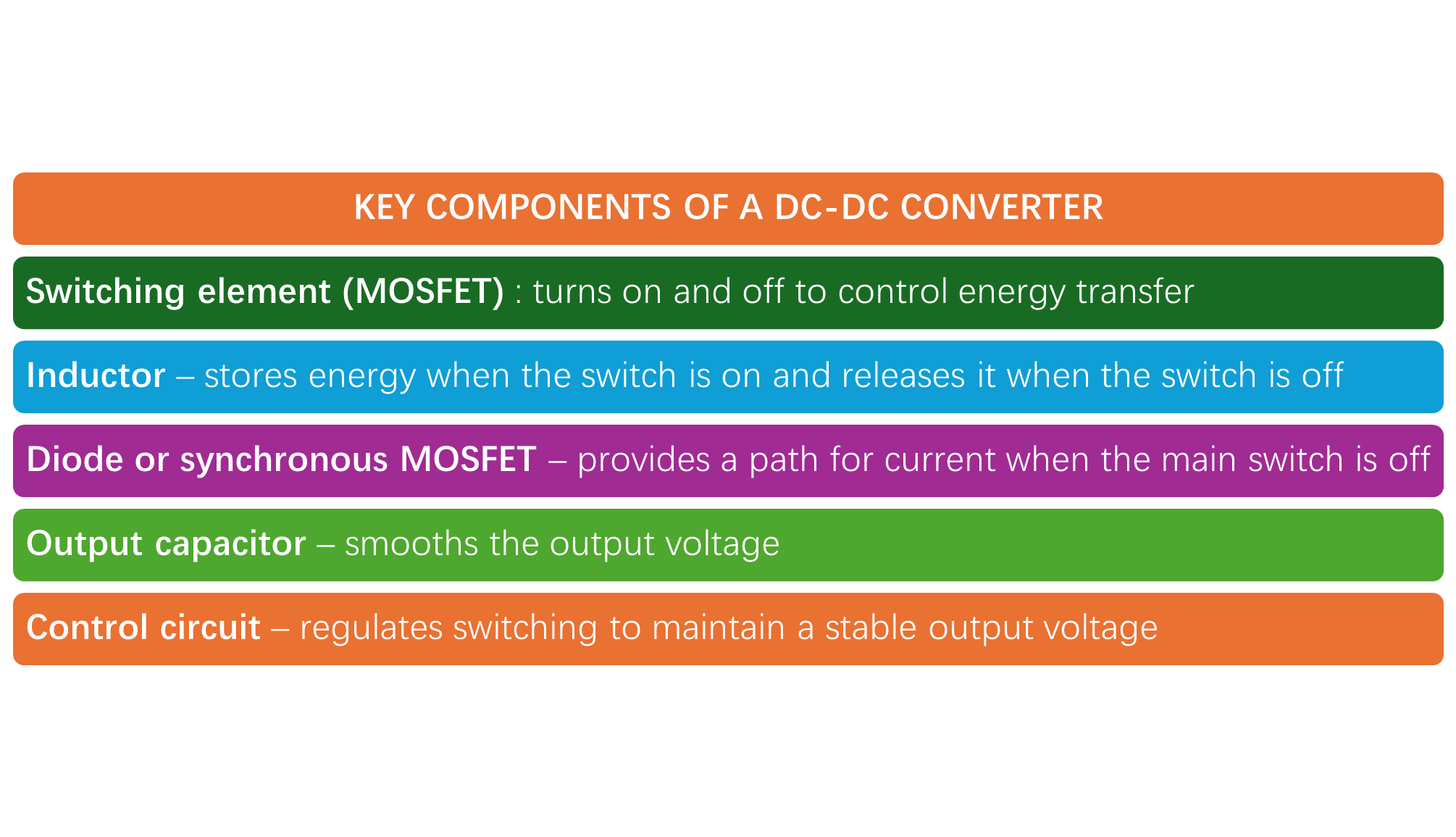
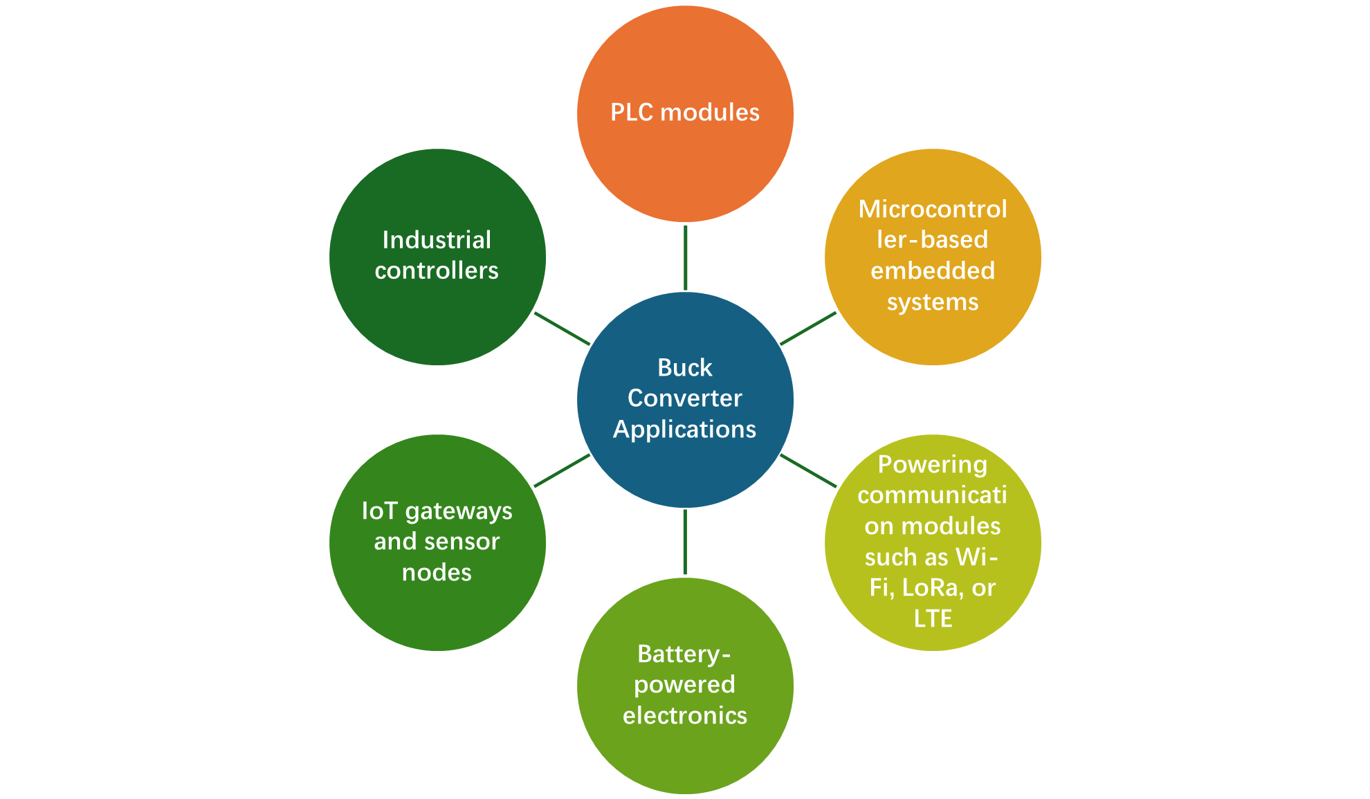
In practical designs, buck converter ICs integrate many of the control functions required for efficient voltage regulation. Modern ICs may include features such as Adjustable output voltage, and overcurrent and thermal protection. Therefore, selecting the right buck converter IC is often a crucial step in DC-DC power supply design. Buck converters are commonly used in applications such as:
Types of DC-DC Converters
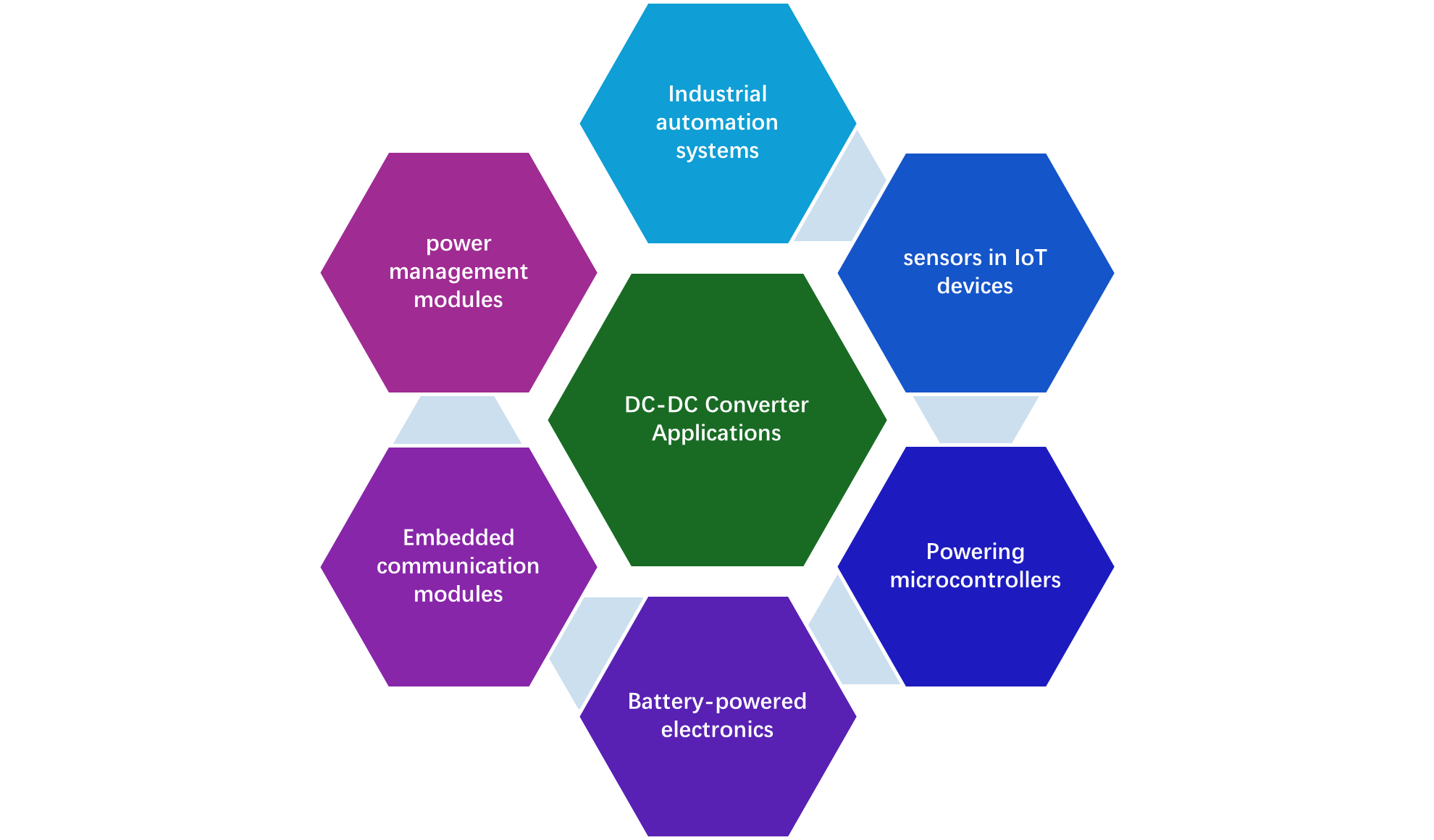
DC-DC converters are essential building blocks in modern electronic systems because they allow designers to efficiently convert one DC voltage level to another. Depending on the application requirements—such as voltage level, efficiency, power consumption, or system architecture—different types of DC-DC converters can be used. Understanding these converter types helps engineers make better decisions during the DC-DC buck converter IC selection process.
DC-DC converters are broadly categorized into following types:
Buck Converter (Step-Down Converter)
A buck converter is designed to reduce a higher input voltage to a lower output voltage. It is the most commonly used DC-DC converter in embedded electronics because many systems require low-voltage rails such as 5V, 3.3V, or 1.8V derived from higher supply voltages like 12V or 24V.
A popular example of a buck converter IC used in many power supply designs is the LM2596 from Texas Instruments. This regulator supports up to 3A output current and is commonly used in 24V to 5V buck converter designs.
Boost Converter (Step-Up Converter)
A boost converter performs the opposite function of a buck converter. It increases a lower input voltage to a higher output voltage. Boost converters are typically used when the available power source has a lower voltage than the required system voltage. Common applications include:
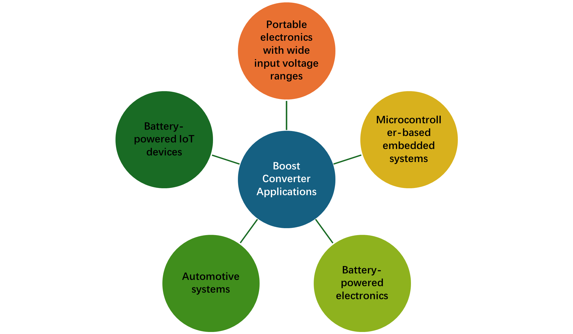
Another well-known high-performance boost regulator is the TPS61090, also from Texas Instruments, designed for portable electronics and battery-powered devices.
Buck-Boost Converter
A buck-boost converter can both increase and decrease voltage depending on the input conditions. This flexibility makes it suitable for systems where the input voltage may fluctuate above or below the required output voltage.
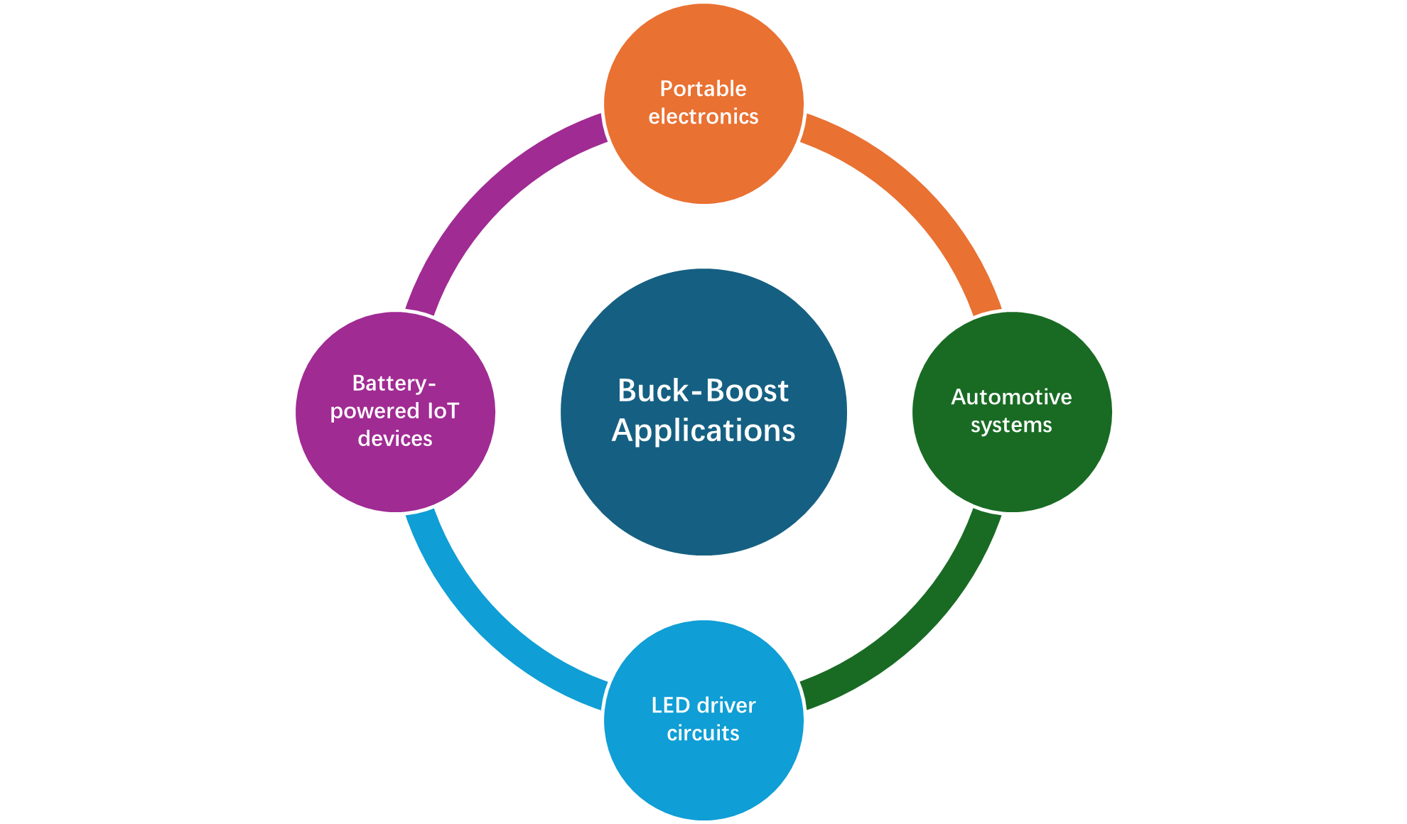
A popular buck-boost converter IC used in many designs is the TPS63060, which efficiently handles input voltages both above and below the output voltage.
Linear Regulators (LDOs)
Linear Voltage Regulators (LDOs) are linear voltage regulators that maintain a stable output voltage even when the input voltage is very close to the output voltage. However, they are less efficient when stepping down large voltage differences because the excess voltage is dissipated as heat. Therefore, many systems use a buck converter followed by an LDO to achieve both efficiency and low-noise output.
One commonly used LDO regulator is the AMS1117, which is widely used to provide 3.3V or 5V regulated output from slightly higher input voltages. Another LDO that is widely used is TLV1117, which offers improved performance for embedded electronics.
Define Your Application Requirements
It is often seen that designers select the DC-DC converter before defining the requirements of the intended application. It is recommended to define the requirements of your application before diving into the selection of a DC-DC converter.
A well-defined set of parameters helps narrow down the options and ensures the selected converter provides stable, efficient, and reliable power. Below are some of the factors you should determine before choosing a buck converter or DC-DC converter IC.
Define Your Application Requirement
Input Voltage Range
The first parameter to identify is the input voltage range that the converter must support. Industrial and IoT systems often operate from different supply sources such as batteries, adapters, or industrial power rails.
If your system uses a 24V industrial power rail, you must choose a regulator that supports a wide input voltage range. A common example is the LM2596, which supports input voltages up to 40V, making it suitable for many industrial step-down applications.

Output Voltage and Output Current
Next, define the required output voltage and load current. These parameters determine the power capability of the converter. Typical output voltages for embedded systems applications are 5V, 3V3, 1.8V, and 1.2V.
For example, if you need a 24V to 5V power supply for an embedded controller, the TPS5430 from Texas Instruments is often used because it supports 3A output current and wide input voltage ranges.
Efficiency Requirements
Efficiency is a critical parameter in power supply design because it directly affects power loss, heat generation, and battery life. In Battery-powered IoT devices and embedded products high efficiency is particularly important.
Modern switching regulators like the TPS62160 achieve efficiencies above 90%, significantly reducing power losses compared to linear regulators.
Switching Frequency
The switching frequency of the converter determines the size of external components, such as inductors and capacitors. Designers must consider the switching frequency before selecting the DC-DC converter for their application. If the application involves high switching frequency, it means the DC-DC converter external components, like inductors and capacitors, will be smaller in size compared to the lower frequency switching applications.
The MP1584EN from Monolithic Power Systems operates at high switching frequencies, enabling very compact power supply designs for embedded electronics.
Operating Temperature Range
Industrial electronics must operate reliably under harsh environmental conditions. Therefore, it is important to select a converter IC rated for the required temperature range.
Typical operating ranges include:
Protection Features
Modern buck converter ICs include several protection mechanisms to protect both the converter and the load circuitry. Designers must choose the DC-DC converter based on the protection features it offers compared to their application requirements. Different DC-DC converters offer different protection features, which include Overcurrent protection (OCP), Thermal shutdown, Short-circuit protection, and Overvoltage protection.
For example, the TPS54202 integrates multiple protection features, making it suitable for industrial embedded systems and IoT devices.
Key Technical Parameters to Evaluate in a Buck Converter IC
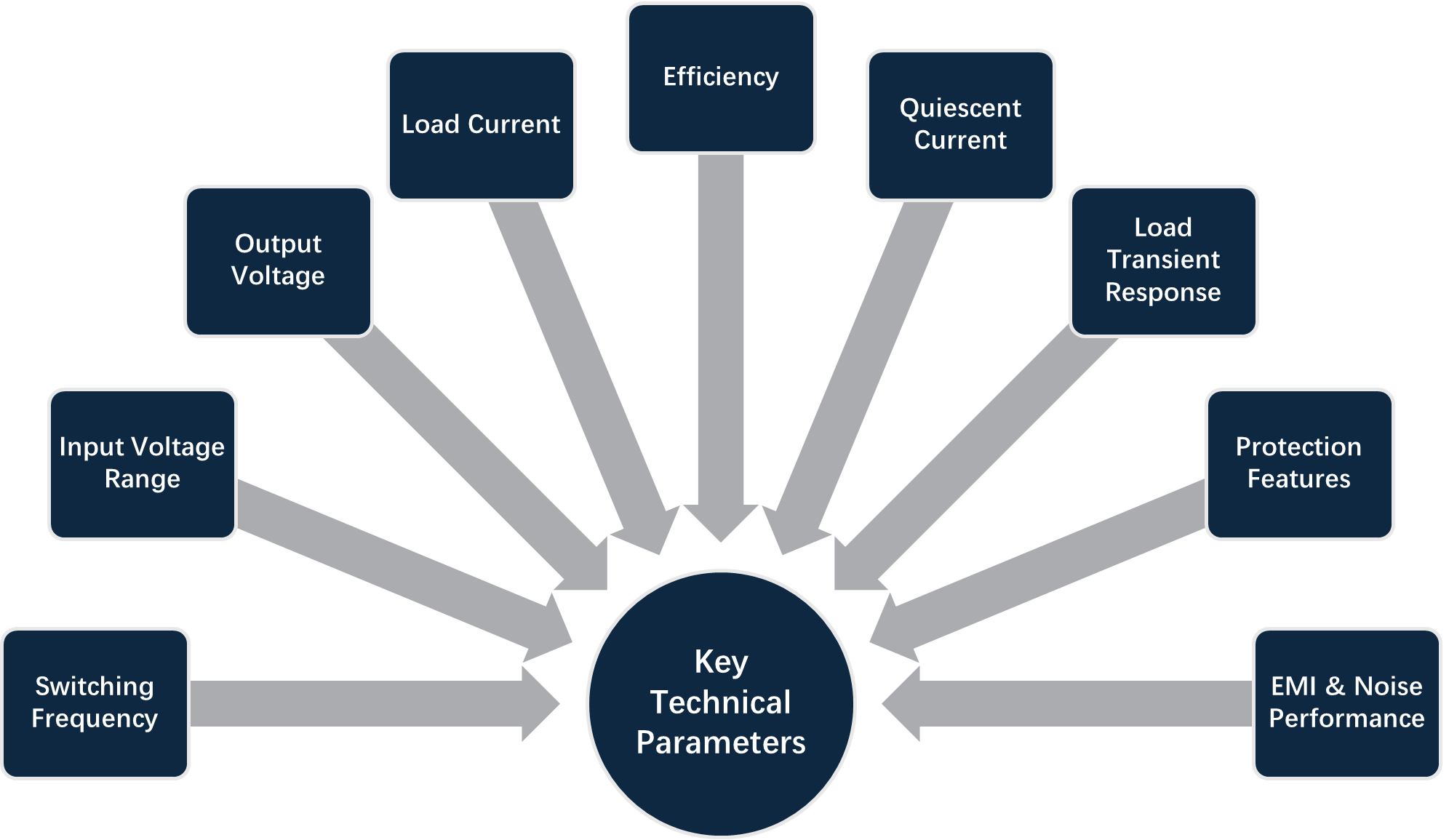
Once you have clearly defined your application requirements, the next step in DC-DC buck converter IC selection is to evaluate the technical parameters that determine the performance, efficiency, and reliability of the regulator. Engineers must carefully analyze the buck converter IC datasheet to ensure the device meets both the electrical and environmental needs of the system.
The most important technical parameters that must be evaluated before DC-DC converter selection are Switching Frequency, Input Voltage Range, output voltage, load current, efficiency, quiescent current, load transient response, protection features, and EMI & Noise performance.
Industrial vs IoT Design Considerations
Selecting a DC-DC buck converter IC requires understanding the differences between industrial systems and IoT devices, as each has unique design priorities. While the underlying buck converter principles remain the same, the application context heavily influences IC selection, efficiency requirements, thermal design, and protection features.
In this section, I made a detailed comparison for designers to guide them on which converter to choose when working on different applications.
Input Voltage & Power Source
Industrial converters must handle wide voltage swings and transient spikes, whereas IoT devices focus on stable, low-voltage operation.
| Feature | Industrial Systems | IoT Devices |
|---|---|---|
| Input Voltage | Typically 12V, 24V, or 48V power rails | Batteries (3.0–4.2V Li-ion) or low-voltage adapters |
| Voltage Variations | Wide tolerance and surge conditions | Moderate variations; often regulated by battery management |
| Example IC | TPS5430 | TPS62840 |
Output Current & Load Requirements
Industrial systems often require higher output current capability, while IoT prioritizes efficiency at light loads.
| Feature | Industrial Systems | IoT Devices |
|---|---|---|
| Load Current | Moderate to high (1–5A+) | Low to moderate (10mA–1A) |
| Peak Loads | Large motors, actuators, sensors | Sensors, microcontrollers, wireless modules |
| IC Example | LM2596 | TPS62840 |
Efficiency & Power Loss
| Feature | Industrial Systems | IoT Devices |
|---|---|---|
| Efficiency Considerations |
Efficiency is important but often secondary to reliability and robustness. Thermal management is handled with heat sinks or board-level copper. |
Efficiency is critical for battery-powered devices. Low quiescent current (Iq) and high light-load efficiency are key. |
| Example IC | LMR33630 – Industrial efficiency >90% | TPS62840 – Ultra-low Iq (~60 nA) for IoT battery savings |
Operating Temperature & Environmental Conditions
Industrial-grade ICs are designed for harsh conditions, while IoT devices can often use compact, low-power ICs with tighter operating constraints.
| Feature | Industrial Systems | IoT Devices |
|---|---|---|
| Temperature Range | −40°C to 85°C or higher | −20°C to 60°C (consumer) or −40°C to 85°C (industrial IoT) |
| Environmental Stress | Dust, vibration, EMI | Usually indoor, lower stress |
| IC Example | TPS5430 | TPS62840 |
Thermal Design & PCB Layout Considerations
In DC-DC buck converter design, thermal management and PCB layout are as important as selecting the right IC. Even the most efficient converter can fail or perform poorly if heat is not properly managed or the PCB layout introduces noise, voltage drops, or EMI. This is critical for industrial systems operating at high currents and IoT devices, where compact boards increase thermal density.
Always check junction-to-ambient thermal resistance (θJA) in the datasheet for proper heat management.
PCB Layout Best Practices
A well-designed PCB layout minimizes voltage ripple, EMI, and thermal stress.
Proper Grounding
It is always recommended to use solid ground plane for return currents and avoid splitting high-current paths and signal grounds.
Thermal Pads & Copper Area
DC-DC converter ICs with exposed thermal pads should be soldered to large copper areas for heat dissipation and use thermal vias to transfer heat to inner layers.
Component Placement
The DC-DC converters’ input and output pins require decoupling capacitors, and these capacitors should be placed close to the IC input pins in the design layout. Also, place the inductor as close as possible to the switch node and output capacitor.
Trace Width Considerations
For converters who offer high current at the output, must use ide traces (calculate using IPC-2221 standards).
Step-by-Step Buck Converter IC Selection Process
Now at this point we are able to select the DC- DC converter IC for out design application. So, selecting the right DC-DC buck converter IC involves more than just picking a part from a distributor catalog. Following a structured step-by-step process ensures your design meets all electrical, thermal, and application-specific requirements while minimizing costly redesigns.
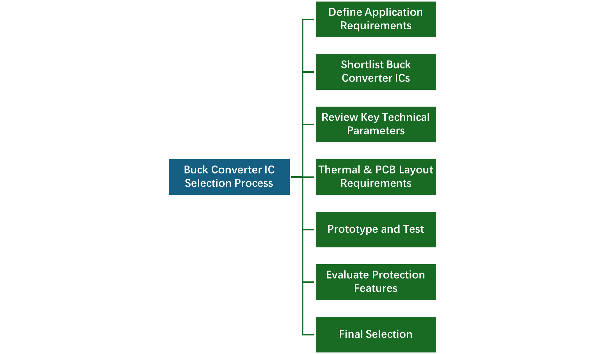
Define Application Requirements
As explained in the above section, identify the input voltage range of your application, its output voltage, maximum load current and transients, and any environmental conditions.
Shortlist DC-DC Converter ICs
Now, read the datasheets of DC-DC converter ICs that fit in your requirements and shortlist them which meet your criteria and eliminate them who does not.
Review Key Technical Parameters
Review the datasheet of your selected DC-DC converter and ensure it satisfy all the technical rquirements such as Switching frequency, Load transient response, Efficiency curves, Protection features and recommended external components like inductor and capacitors.
Consider Thermal & PCB Layout Requirements
Analyse the heat dissipation at maximum load and verify it with your selected IC by reading its datasheet to ensure that it meet all the thermal requirements of the intended design applicaiton.
Prototype and Test
Now, as the DC-DC converter IC has been selected. It is time to build a small-scale test board with the selected IC. Measure output voltage under different load conditions and verify its efficiency and thermal performance.
Evaluate Protection Features
Confirm overcurrent, overvoltage, and thermal protection operate correctly using the IC datasheet.
Popular DC‑DC Buck Converter ICs for Industrial & IoT Applications
This section will help the engineers, designers, and hobbyists to quickly identify practical solutions during the DC‑DC buck converter IC selection process. I have studied different DC-DC converters datasheets to come up with a guide that helps designers to choose suitable converters for various voltages, power levels, and application types — from industrial automation to compact IoT nodes.
LM2596 – Industrial Step‑Down Regulator
This is widely used in industrial applications. Its key specifications are Input voltage: 4.5V–40V, output current: up to 3A, and switching frequency: ~150 kHz. The pinout of LM2596, along with its required external components are shown below.
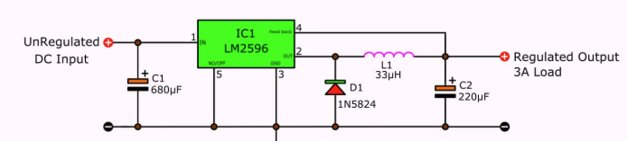
LM2596 is ideal for stepping 24V→5V rails in automation systems. Its simplicity and robustness make it a frequent choice in legacy and low‑cost industrial designs.
TPS5430 – Industrial 3A Regulator with Enhanced Performance
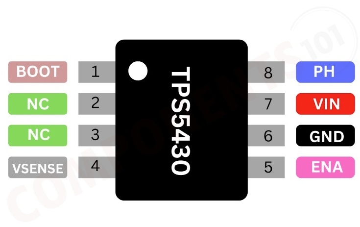
This DC-DC is widely used in industrial applications to enhance performance and wide input voltage range. Its key specifications are Input: 5.5V–36V, output current: up to 3A, and switching frequency: ~570 kHz. The pinout of TPS5430, along with its required external components are shown below.
TPS62840 – Ultra‑Low Quiescent Current for IoT Nodes
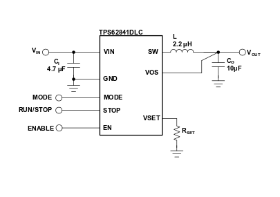
This regulator is an excellent choice for battery‑powered IoT devices where efficiency in light load and low standby current are critical. So, it extends battery life in sensor nodes, wearables, and energy‑harvesting systems. Its key specifications are Input: 1.8V–6.5V, output current: up to 750 mA, and Ultra‑low Iq (≈60 nA shutdown). The pinout of TPS62840, along with its required external components are shown below.
MP1584EN – Compact High‑Frequency Regulator for Space‑Constrained Boards
This DC-DC converter is popular because its high switching frequency enables small inductors and capacitors, making it ideal for compact IoT and embedded boards where PCB space is limited. Ideal for IoT gateways, wearable power rails, and compact embedded modules.
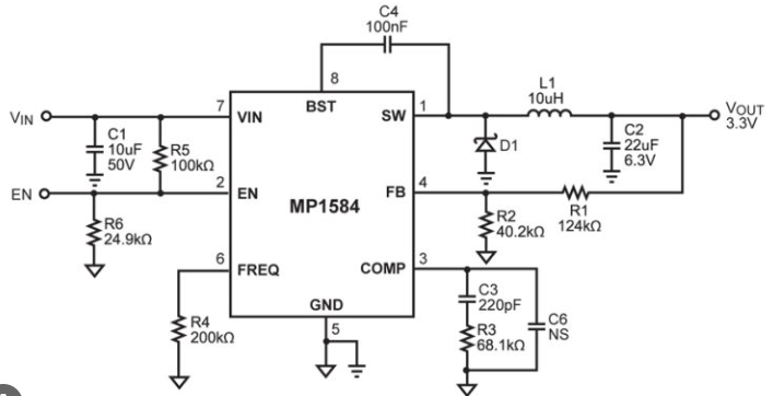
Its key specifications are Input: 4.5V–28V, output current: up to 3A, and Switching frequency: ~1.5 MHz. The pinout of MP1584, along with its required external components are shown below.
Conclusion
To sum up, selecting the right DC-DC buck converter IC is a critical step in designing reliable and efficient industrial and IoT systems. From defining application requirements to evaluating technical parameters, thermal design, and PCB layout, every stage of the selection process impacts the performance, efficiency, and longevity of your system. This article is a technical guide for the designers who want to use the DC-DC converter in their application but have little knowledge of regulators. This guide will help them choose the right regulator for their applications that perform the function as per the set specifications.
FAQ (Frequently Asked Questions)
Industrial regulators have High voltage input tolerance (12–48V), high output current (up to 5A+), wide temperature range (−40°C to 85°C+), and IoT DC-DC converters have Low-voltage input (batteries 3–4.2V), low-to-moderate current (10mA–1A), ultra-low quiescent current for battery life, compact boards, and noise-sensitive designs.
The most important key parameters to check are : input voltage range, output current and transient handling, switching frequency, and junction-to-ambient thermal resistance (θJA) for thermal design
Choose an inductor with a saturation current at least equal to the maximum load and sized for the desired ripple current. Use low-ESR ceramic or electrolytic capacitors for input and output, ensuring their voltage rating exceeds the maximum voltage. Always start with the manufacturer’s recommended component values from the datasheet and fine-tune them as needed for your specific design.