When you work with parallel circuits, you’re really working with a question of where the current goes.
The source provides a total current IT, and at a junction that current splits into branch current values based on the resistances (or impedances) in each branch.
That split is called current division, and the shortcut engineers use is the current divider formula.
You’ll also see the same idea described as the current divider rule or current division formula. These are on-page synonyms, and they all point to the same concept.
In this article, you’ll learn what a current divider is, the current divider formula for two resistors, the general multi-branch equation, a brief derivation so you know the assumptions, worked examples you can copy, the AC impedance form, and the common mistakes that cause wrong answers.
What Is a Current Divider Formula?
A current divider is any network of two or more components in parallel where a single input current splits into multiple branch currents.
Kirchhoff’s Current Law (KCL) is the foundation here: the net current at a node is zero, meaning the current entering a node equals the current leaving it.
\[ I_T = I_1 + I_2 + \dots + I_n \]
The key parallel-circuit fact is that each branch sees the same voltage across the same two nodes.
So if branch voltages are equal, the only reason branch currents differ is because the branch resistances differ, by Ohm’s law:
\[ I = \frac{V}{R} \]
That is why the branch with lower resistance carries more current, and why the current divider rule is such a useful shortcut in parallel circuit analysis.
Current Divider Formula for Two Parallel Resistors
For two resistors R1 and R2 in parallel, with total current IT entering the parallel network, the current divider formula is:
\[ I_1 = I_T \times \frac{R_2}{R_1 + R_2} \]
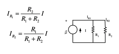
\[ I_2 = I_T \times \frac{R_1}{R_1 + R_2} \]
This is often introduced as the current divider rule: each branch gets a fraction of the total current.
The question is why does the “other resistor” appear in the numerator? Because current division is inverse to resistance in parallel circuits. The branch current ratio is:
\[
\frac{I_1}{I_2} = \frac{R_2}{R_1}
\]
So if R1 is smaller, I1 must be larger, and the “opposite resistor in the numerator” naturally produces that inverse behavior.
Current Divider Formula for Multiple Parallel Branches
For N resistors in parallel, the cleanest general form uses conductance:
\[ G_i = \frac{1}{R_i} \]
Total conductance adds directly in parallel:
\[ G_{total} = \sum_{i=1}^{N} \frac{1}{R_i} \]
Then the branch current (the current division formula) is:
\[ I_x = I_T \times \frac{\frac{1}{R_x}}{\frac{1}{R_1} + \frac{1}{R_2} + \dots + \frac{1}{R_N}} \]
This says: each branch gets a share of the total current proportional to its conductance (inverse resistance).
Equivalent resistance version
First compute the parallel equivalent resistance:
\[ \frac{1}{R_{eq}} = \frac{1}{R_1} + \frac{1}{R_2} + \dots + \frac{1}{R_N} \]
Then:
\[ R_{eq} = \frac{1}{\sum (1/R_i)} \]
This matches how many circuit texts describe the current divider formula as “branch current relates to total current by the ratio of total resistance to branch resistance.”
Practical step-by-step method
- Compute Req (or compute Gtotal).
- If the source is a voltage source, compute total current first:
\[ I_x = I_T \times \frac{R_{eq}}{R_x} \]
- Compute each branch current using conductance ratio:
\[
I_i = I_T \times \frac{G_i}{G_{\text{total}}}
\]
- Verify with KCL:
\[
I_1 + I_2 + \cdots + I_N = I_T
\]
Derivation of the Current Divider Formula
For two resistors in parallel, each branch has the same voltage V.
\[ I_T = \frac{V}{R_1} + \frac{V}{R_2} \]
\[ I_T = V \left( \frac{1}{R_1} + \frac{1}{R_2} \right) \]
\[ V = I_T \times \frac{R_1 R_2}{R_1 + R_2} \]
By KCL:
\[
I_T = I_1 + I_2
\]
Substitute:
\[
I_T = \frac{V}{R_1} + \frac{V}{R_2}
\]
Solve for V, then substitute back into I1 or I2, and you arrive at:
\[
I_1 = I_T \times \frac{R_2}{R_1 + R_2}
\quad,\quad
I_2 = I_T \times \frac{R_1}{R_1 + R_2}
\]
This is exactly why the current divider rule is really just “equal branch voltage + Ohm’s law + KCL.”
Current Divider Formula Examples
Example 1: Two Resistors in Parallel (Direct Current Divider Formula)
Given:
IT=6 A, R1=3 Ω, R2=6 Ω
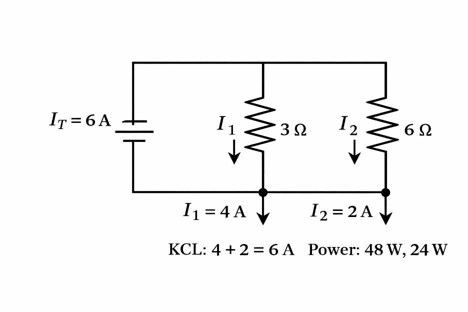
\[
I_1 = 6 \times \frac{6}{3 + 6} = 4\,A
\qquad
I_2 = 6 \times \frac{3}{3 + 6} = 2\,A
\]
KCL check:
\[
I_1 + I_2 = 4 + 2 = 6\,A
\]
Power check:
\[
P_1 = I_1^2 R_1 = 4^2 \times 3 = 48\,W
\qquad
P_2 = I_2^2 R_2 = 2^2 \times 6 = 24\,W
\]
That power result is a reminder: current division tells you the currents, but component ratings still decide whether the circuit survives.
Example 2: Three Resistors in Parallel (Conductance Form)
Given:
IT=15 A , R1=10 Ω, R2=25 Ω, R3=100 Ω
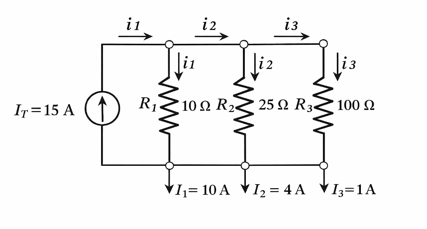
\[
G_1 = \frac{1}{10} = 0.1
\qquad
G_2 = \frac{1}{25} = 0.04
\qquad
G_3 = \frac{1}{100} = 0.01
\]
\[
G_{\text{total}} = 0.1 + 0.04 + 0.01 = 0.15
\]
\[
I_1 = 15 \times \frac{0.1}{0.15} = 10\,A
\qquad
I_2 = 15 \times \frac{0.04}{0.15} = 4\,A
\qquad
I_3 = 15 \times \frac{0.01}{0.15} = 1\,A
\]
KCL check:
\[
10 + 4 + 1 = 15\,A
\]
This example shows the intuitive rule: smaller resistance means larger branch current.
Current Divider in AC Circuits
The current divider rule also works in AC circuits, but you replace resistance R with impedance Z. For two parallel impedances Z1 and Z2:
\[
i_1 = i_T \times \frac{Z_2}{Z_1 + Z_2}
\qquad
i_2 = i_T \times \frac{Z_1}{Z_1 + Z_2}
\]
Many engineers prefer admittance Y because it adds directly in parallel:
\[
Y = \frac{1}{Z}
\]
\[
i_x = i_T \times \frac{Y_x}{Y_{\text{total}}}
\]
Example idea (RC parallel, frequency intuition)
For a resistor R in parallel with a capacitor C:
\[
Z_C = \frac{1}{j\omega C}
\]
The resistor branch current comes out as:
\[
i_R = \frac{1}{1 + j\omega C R}\, i_T
\]
At low frequency, the capacitor impedance is large, so most current goes through RRR.
At high frequency, the capacitor impedance becomes small, so it “steals” more of the current.
Common Mistakes and How to Catch Them
Confusing series and parallel
Current divider formulas only apply when branches share the same two nodes. If they don’t, go back to KCL/nodal analysis.
Using a voltage divider formula by mistake
Voltage divider uses the resistor of interest in the numerator (series circuits).
Current divider uses the opposite branch resistance in the numerator (parallel circuits).
Skipping the KCL check
Always do:
\[
\sum I_{\text{branch}} = I_T
\]
If the sum doesn’t match, something is wrong.
Ignoring power dissipation
After you find branch currents, check:
\[
P = I^2 R
\]
Power issues are one of the most common “it worked on paper” failures in real designs.
If current is high, don’t use a generic resistor as a shunt. Choose a proper current sense resistor (low-ohm, rated wattage, low TCR) and confirm P with margin.
Many designers pair it with a current monitor IC for clean measurement.
Current Divider vs Voltage Divider
A current divider splits current in parallel circuits. A voltage divider splits voltage in series circuits.
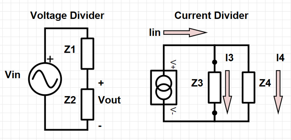
Voltage divider (series, across R2):
\[
V_{\text{out}} = V_{\text{in}} \times \frac{R_2}{R_1 + R_2}
\]
Current divider (parallel, through R1):
\[
I_1 = I_T \times \frac{R_2}{R_1 + R_2}
\]
Same “shape,” different physical situation. The safest habit is to say out loud what is common: voltage is common in parallel, current is common in series.
Conclusion
The current divider formula is a practical shortcut for finding branch current in parallel circuits. It works because the branch voltage is the same, and KCL forces the total current to split across available paths.
If you remember three habits, you’ll be accurate most of the time:
- Confirm the network is truly parallel (same two nodes across each branch).
- Use the right current divider rule (resistance, conductance, or impedance).
- Validate with a KCL sum check and a power check.
If you’re taking this from paper to hardware, the next step is usually measuring or limiting that branch current.
For current measurement, you’ll typically choose a current sense (shunt) resistor or a current monitor IC such as INA219 class devices.
For AC or isolated sensing, a Hall-effect sensor ACS712 type is often the cleaner option.
Flywing Tech stocks current-sense resistors and current-monitor parts so use these calculations to select values, then verify power rating and measurement range before you prototype.
Frequently Asked Questions
1. What is a current divider?
A current divider is a parallel circuit configuration where the total supply current splits into multiple branch currents. Each branch carries a portion of the total current based on its resistance or impedance.
2. Why does current divide in parallel circuits?
In a parallel circuit, all branches share the same voltage. Because current is inversely related to resistance, branches with lower resistance draw more current, while higher-resistance branches draw less.
3. When should I use the current divider formula?
Use the current divider formula when you know the total current entering a parallel network and want to calculate how much current flows through each branch.
4. Does the current divider work only with two resistors?
No. The current divider principle applies to any number of parallel branches. For multiple resistors, current divides based on each branch’s conductance relative to the total conductance.
5. Can I use the current divider in AC circuits
Yes. In AC circuits, resistances are replaced by impedances. The current divider still applies, but phase and frequency effects must be considered.
6. What is the most common mistake when using the current divider rule?
The most common mistake is confusing parallel and series circuits or accidentally using the voltage divider formula instead of the current divider rule.
7. How do I know if my current divider result is correct
A quick check is to verify that all branch currents add up to the total current. This confirms compliance with Kirchhoff’s Current Law.
8. Why do engineers check power dissipation in current divider circuits?
Even if the current calculation is correct, a resistor may overheat if it is not rated for the resulting power. Power checks help prevent component failure in real designs.
9. What happens if one branch resistance is very small?
Most of the total current will flow through that branch. Extremely low resistance paths can dominate the current split and may require higher power-rated components.
10. How is a current divider different from a voltage divider?
A current divider applies to parallel circuits and splits current, while a voltage divider applies to series circuits and splits voltage. Each rule works only in its respective configuration.